Optical transmission equipment and integrated circuit
- Summary
- Abstract
- Description
- Claims
- Application Information
AI Technical Summary
Benefits of technology
Problems solved by technology
Method used
Image
Examples
embodiment 1
[0065]FIG. 1 shows a structure of an optical transmitter applied to optical transmission equipment according to a first embodiment of the present invention.
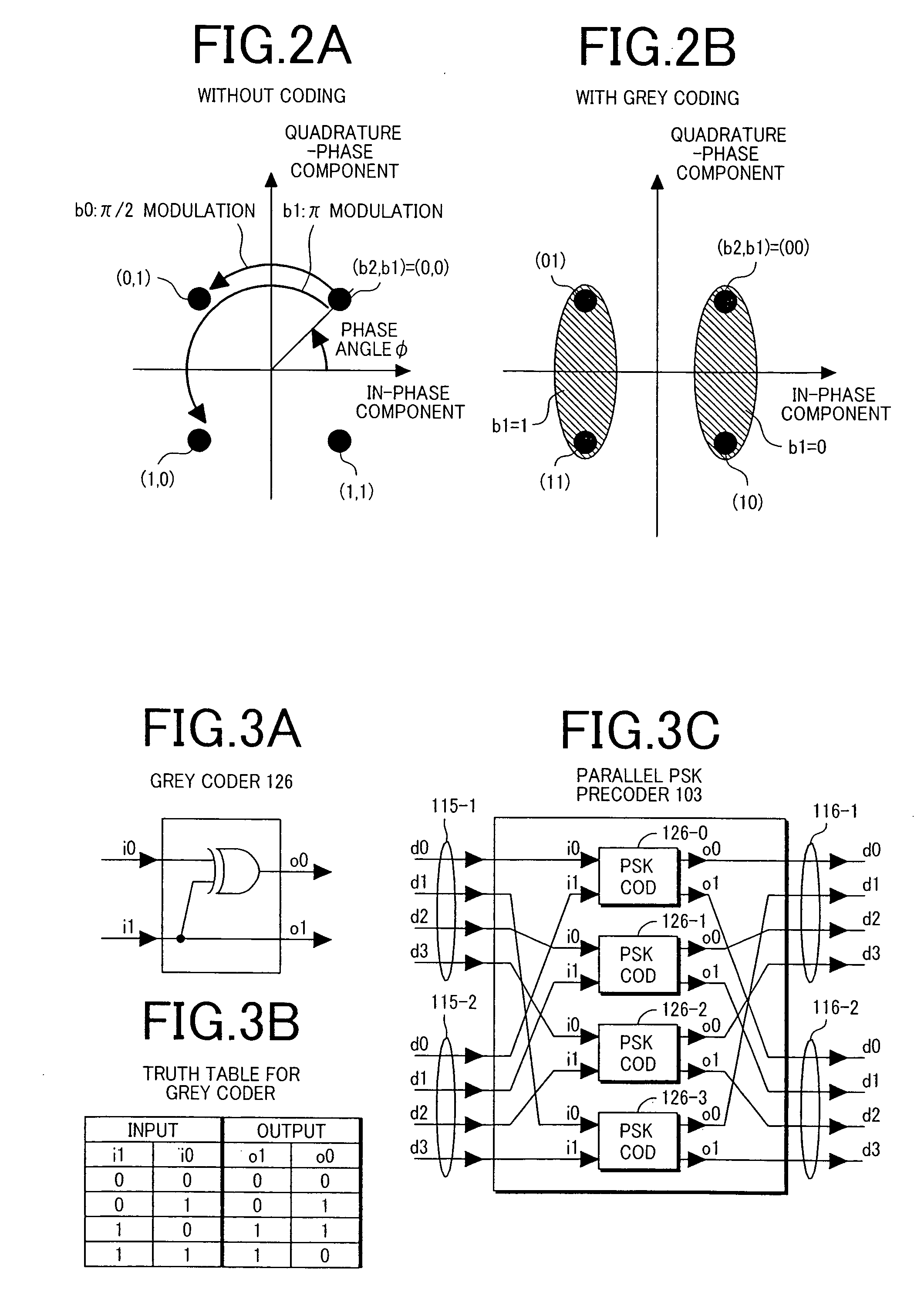
[0066] The optical transmitter 100 shown here comprises two encoders 103 and 104 using different encoding formats. The encoder 103 is a parallel precoder for four-level phase modulation (PSK precoder) and the encoder 104 is a parallel precoder for four-level intensity modulation (ASK precoder).
[0067] An optical modulation unit is comprised of two optical phase modulators 109-1 and 109-2, and one optical intensity modulator 110. An CW (continuous wave) optical signal generated from a semiconductor laser 108 is subjected to four-level phase modulation by the two optical phase modulators 109-1 and 109-2 associated with the PSK precoder 103 and four-level intensity modulation by the optical intensity modulator 110 associated with the ASK precoder 104 and sent out as a 16-level optical phase / intensity modulated signal 113 to an outp...
embodiment 2
[0145]FIG. 11 shows an example of an optical network to which optical transmission equipment 160 according to the present invention have been applied.
[0146] Optical transmission equipment 160-1 comprises a plurality of optical transmitters 100 (100-1 and 100-2) and optical receivers 200 (200-1 and 200-2) connected to a switch circuit 162-1. Likewise, optical transmission equipment 160-2 also comprises a plurality of optical transmitters 100 (100-3 and 100-4) and optical receivers 200 (200-3 and 200-4) connected to a switch circuit 162-2. The optical transmitter 100-1 and the optical receiver 200-3, which are in mutually opposing positional relation, and the optical transmitter 100-4 and the optical receiver 200-2, which are also in mutually opposing positional relation, are connected to each other via optical fiber transmission paths 164-1 and 162-2, respectively.
[0147] Each of the optical transmission equipment 160 is capable of switching between a working system and a standby sy...
embodiment 3
[0153]FIG. 13 shows an example of an optical network comprised of WDM type optical transmission equipment 165 (165-1 and 165-2) to which the present invention has been applied.
[0154] The optical transmission equipment 165-1 and 165-2 are coupled to each other through an upward optical fiber transmission path 164-1 and a downward optical fiber transmission path 164-2. The optical transmission equipment is further connected to other optical transmission equipment by a pair of upward and downward optical fiber transmission paths, as shown by the optical fiber transmission paths 164-3 and 164-4 in the drawing. Each of the optical fibers transmits three optical signals at different wavelengths as wavelength multiplexed optical signals.
[0155] As shown in the optical transmission equipment 165-1, each of the optical transmission equipment 165 comprises a plurality of optical receivers (RX) 200 (200-1 to 200-3 and 200-4 to 200-6) each coupled to the receiving-side optical fiber transmissi...
PUM
 Abstract
Description
Claims
Application Information
 - R&D
- Intellectual Property
- Life Sciences
- Materials
- Tech Scout
- Unparalleled Data Quality
- Higher Quality Content
- 60% Fewer Hallucinations
Browse by: Latest US Patents, China's latest patents, Technical Efficacy Thesaurus, Application Domain, Technology Topic, Popular Technical Reports.
© 2025 PatSnap. All rights reserved.Legal|Privacy policy|Modern Slavery Act Transparency Statement|Sitemap|About US| Contact US: help@patsnap.com


