Process for producing transparent electrode

a technology of transparent electrodes and electrode layers, which is applied in the direction of instruments, non-metal conductors, conductive layers on insulating supports, etc., can solve the problems of inability to easily etch, inconvenient lift-off process, and scarce indium resources, and achieve excellent transparency and electrical conductivity. , the effect of low cos

Inactive Publication Date: 2006-11-30
ASAHI GLASS CO LTD
View PDF4 Cites 20 Cited by
  • Summary
  • Abstract
  • Description
  • Claims
  • Application Information

AI Technical Summary

Benefits of technology

[0032] According to the process for producing a transparent electrode of the present invention, a transparent electrode exce...

Problems solved by technology
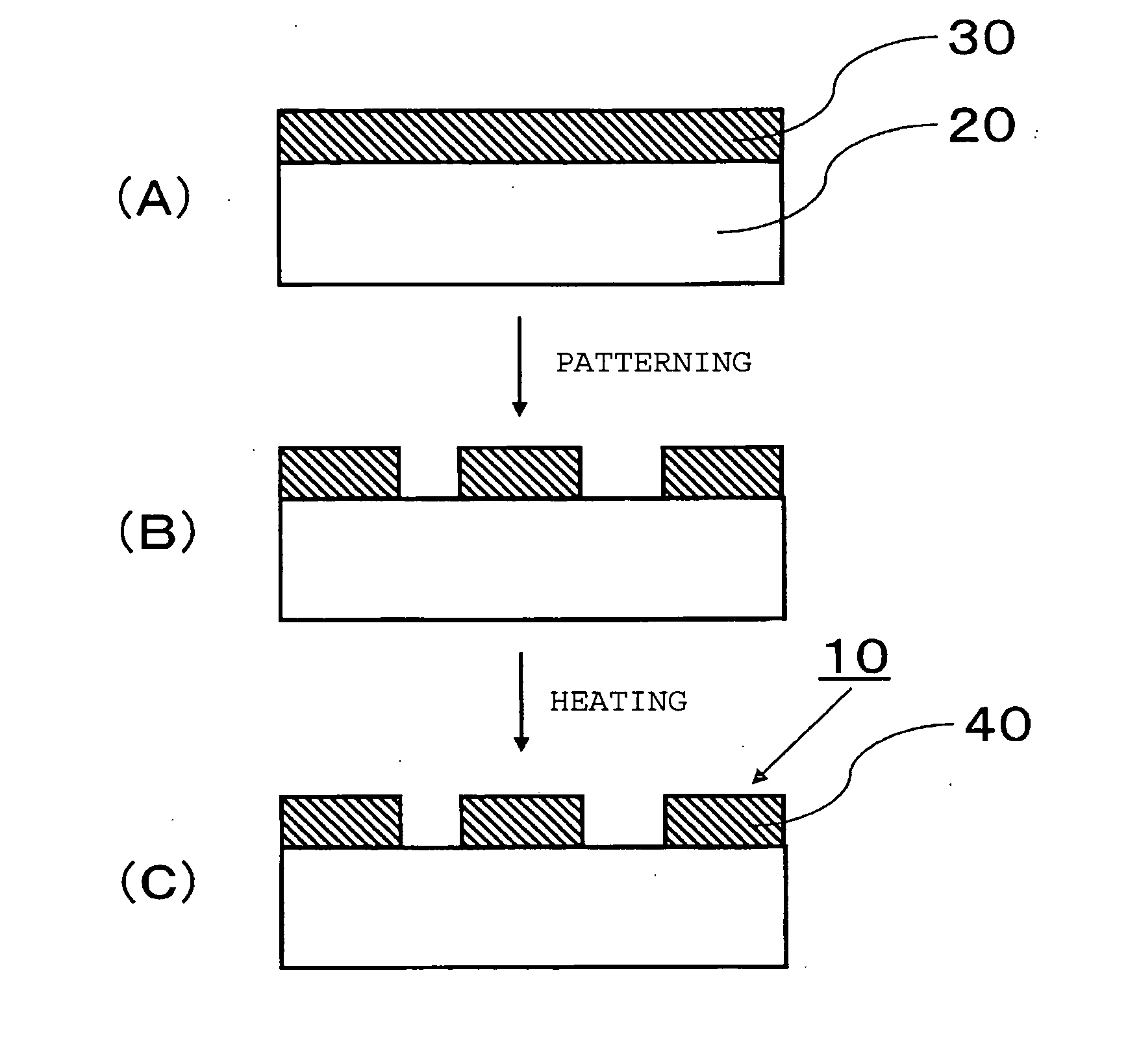
However, it has been known that indium resources are scarce, and development of an alternative has been desired.
However, a tin oxide film is chemically stable and thereby can not easily be etched.
However, lift-off process is not suitable for products for which high pattern accuracy is required, as protrusions called spikes are formed at the edge of the formed pattern, which may cause electric failure.
Further, mechanical washing such as brush washing will be required to remove the spikes, an...

Method used


Image

  • Process for producing transparent electrode
  • Process for producing transparent electrode
  • Process for producing transparent electrode

Examples


example 1

[0079] A high strain point glass (PD200, manufactured by Asahi Glass Company, Limited) having a thickness of 2.8 mm was prepared as a substrate. The glass substrate was washed and set in a substrate holder. A SnO2 oxide sintered target (manufactured by MITSUI MINING & SMELTING CO., LTD.) having 3 atomic % of Sb added to Sn was attached to the cathode of a DC magnetron sputtering apparatus. The deposition chamber of the sputtering apparatus was evacuated of air, and a film containing tin oxide as the main component having a thickness of about 150 nm was formed on the glass substrate by a DC magnetron sputtering method. As the sputtering gas, an argon gas was used. The substrate temperature was 80° C. The pressure was 1.2 Pa at the time of deposition. The obtained film was a film colored yellow, whereby presence of oxygen deficiencies in the film was estimated. The visible light transmittance of the glass substrate provided with the obtained film was 81%. The density of the formed fil...

example 2

[0087] A high strain point glass (PD200, manufactured by Asahi Glass Company, Limited) having a thickness of 2.8 mm was prepared as a substrate. The glass substrate was washed and set in a substrate holder. A SnO2 oxide sintered target having 10 atomic % of Sb added to Sn (a 6 inch circular SnO2 target (manufactured by MITSUI MINING & SMELTING CO., LTD.) formed by mixing Sb2O3 and SnO2 powders in a molar ratio of 10:90 and sintering the mixture) was attached to the cathode of a DC magnetron sputtering apparatus. The deposition chamber of the sputtering apparatus was evacuated of air, and a film containing tin oxide as the main component having a thickness of about 150 nm was formed on the glass substrate by a DC magnetron sputtering method. As the sputtering gas, an argon gas was used. Deposition was carried out at room temperature without heating the substrate, and the temperature was 70° C. The pressure was 3.3 Pa at the time of deposition. The visible light transmittance of the g...

example 3

[0091] A high strain point glass (PD200, manufactured by Asahi Glass Company, Limited) having a thickness of 2.8 mm was prepared as a substrate. The glass substrate was washed and set in a substrate holder. A SnO2 oxide sintered target having 10 atomic % of Sb added to Sn (a 6 inch circular SnO2 target (manufactured by MITSUI MINING & SMELTING CO., LTD.) formed by mixing Sb2O3 and SnO2 powders in a molar ratio of 10:90 and sintering the mixture) was attached to the cathode of a DC magnetron sputtering apparatus. The deposition chamber of the sputtering apparatus was evacuated of air, and a film containing tin oxide as the main component having a thickness of about 150 nm was formed on the glass substrate by a DC magnetron sputtering method. As a sputtering gas, an argon gas was used. Deposition was carried out at room temperature without heating the substrate, and the temperature was 70° C. The electric power was 1,000 W. The gas pressure was changed within a range of from 1 to 4 Pa...


PUM

PropertyMeasurementUnit
Temperatureaaaaaaaaaa
Fractionaaaaaaaaaa

Abstract

To provide a process for producing a transparent electrode comprising a tin oxide film which can readily be patterned, which can be realized at a low cost, and which has low resistivity and is excellent in transparency. A process for producing a transparent electrode having a patterned tin oxide film formed on a substrate, which comprises a step of forming a tin oxide film having light absorption characteristics on a substrate, a patterning step of removing part of the tin oxide film having light absorption characteristics, and a step of subjecting the patterned tin oxide film having light absorption characteristics to heat treatment to obtain a tin oxide film.

Description

BACKGROUND OF THE INVENTION [0001] 1. Field of the Invention [0002] The present invention relates to a process for producing a transparent electrode suitable particularly for a flat panel display. [0003] 2. Discussion of Background [0004] Heretofore, for flat panel displays such as liquid crystal display devices, plasma displays and organic LED, a substrate provided with a transparent conductive film has been used as a transparent electrode. As material of the transparent conductive film, indium oxide, zinc oxide and tin oxide materials have been known. ITO (indium tin oxide) as the indium oxide material is particularly famous and used widely. It is because of low resistivity properties and favorable patterning properties that ITO is widely used. However, it has been known that indium resources are scarce, and development of an alternative has been desired. [0005] Tin oxide (SnO2) is a material promising as the alternative. In order to form a pattern of e.g. a conductive circuit or ...

Claims


Application Information

Patent Timeline
IPC IPC(8): H01L21/44C03C17/245G02F1/1343H01B5/14H01B13/00H01J9/02H01L31/18
CPCC03C17/245C03C2217/231C03C2218/154C03C2218/328Y02E10/50G02F1/13439H01J9/02H01J2217/04H01L31/1884C03C2218/33C23C14/086C23C14/3414H01B1/08H01B5/14H01B13/0016
Inventor MITSUI, AKIRAODAKA, HIDEFUMIYONEMORI, SHIGEAKIAKAO, YASUHIKO
Owner ASAHI GLASS CO LTD
Why Eureka
Try Eureka