Deposition method by physical vapor deposition and target for deposition processing by physical vapor deposition

a deposition method and physical vapor technology, applied in vacuum evaporation coatings, electrolysis components, coatings, etc., can solve problems such as difficult control of the state of occurrence of irregularities to a perfect planarization, unstable deposition rate, and occurrence of red-heated portions at non-uniform places, so as to ensure mass production stability and improve the deposition rate and in-plane uniformity of targets. , the effect of improving the deposition ra

Inactive Publication Date: 2006-12-07
PANASONIC CORP
View PDF3 Cites 12 Cited by
  • Summary
  • Abstract
  • Description
  • Claims
  • Application Information

AI Technical Summary

Benefits of technology

[0034] According to the present invention, it becomes implementable to improve the deposition rate a

Problems solved by technology

However, with the use of the method described in Document 1 or Document 2 that a powdery or granular target is generally planarized, because of the target material being powdery or granular, it is difficult to control the state of occurrence of irregularities to a perfect planarization.
Therefore, if the state of occurrence of irregularities cannot be controlled, places of occurrence of the red-heated portions also cannot be controlled so that the red-h

Method used


Image

  • Deposition method by physical vapor deposition and target for deposition processing by physical vapor deposition
  • Deposition method by physical vapor deposition and target for deposition processing by physical vapor deposition
  • Deposition method by physical vapor deposition and target for deposition processing by physical vapor deposition

Examples


first embodiment

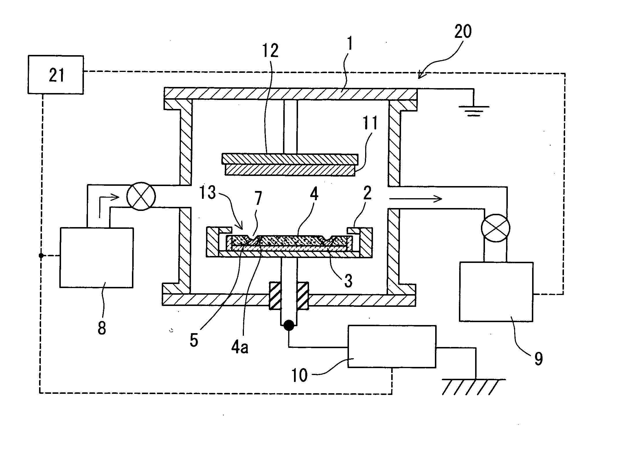
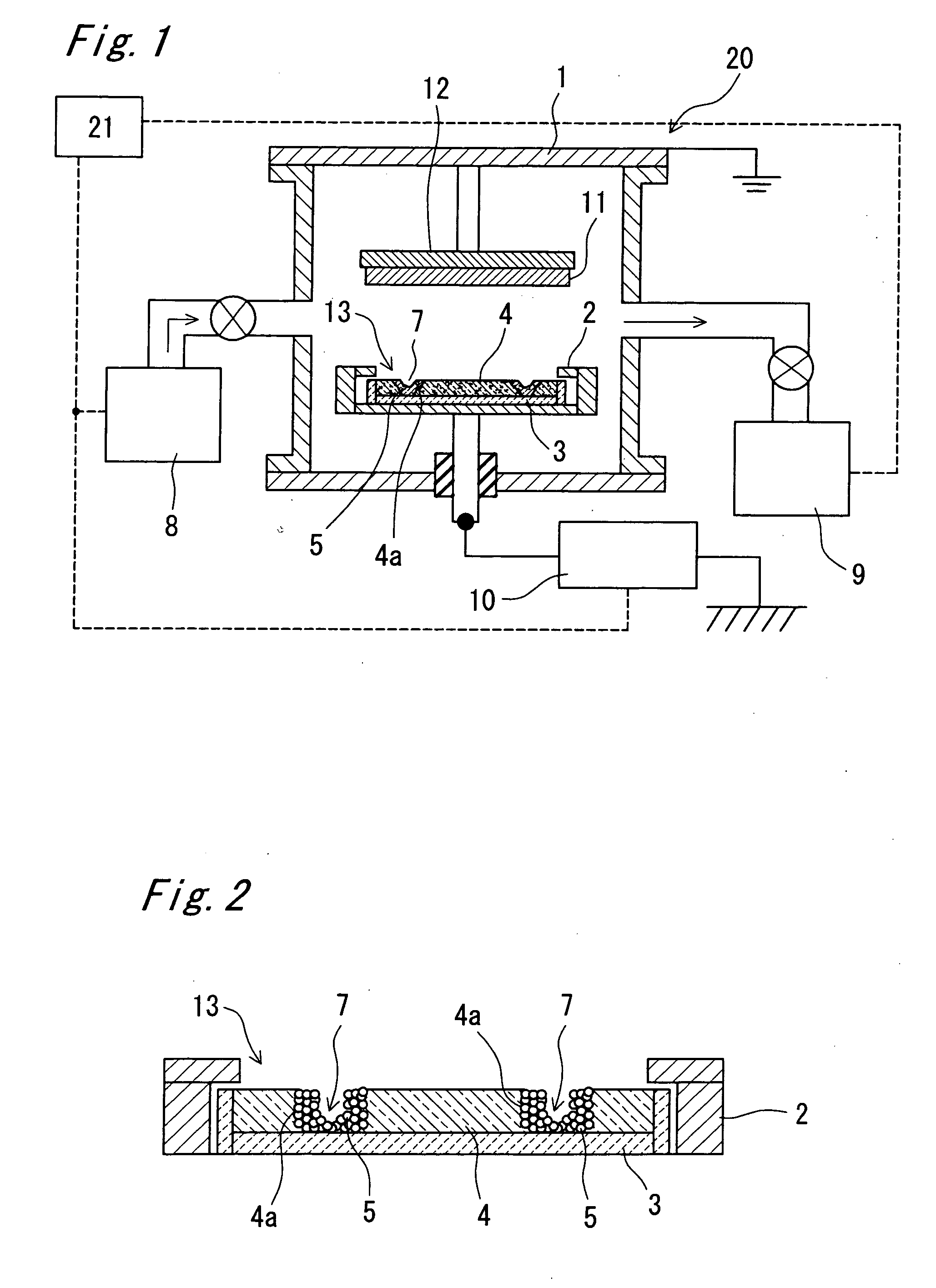
[0059]FIG. 1 shows a schematic configurational view showing the configuration of a deposition apparatus (sputtering apparatus) 20 which is an example of the deposition apparatus by a sputtering process which is an example of the physical vapor deposition method according to a first embodiment of the present invention.

[0060] As shown in FIG. 1, the deposition apparatus 20 includes a vacuum chamber 1 which is an example of a processing chamber internally having a reduced-pressure space, e.g. vacuum atmosphere, for deposition process by sputtering to be carried out therein, a grounding shield 2 placed close to a sintered body target in the later-described target (or sputtering target), a target mounting plate 3 which is an example of a target support member on which the target is to be mounted within the vacuum chamber 1, and a base material holding member 12 which is an example of a member for holding a base material (material to be processed) 11 which is to be subjected to depositio...

second embodiment

[0101] The present invention may be carried out in other various modes without being limited to the above embodiment. For example, FIG. 9 is a schematic sectional view showing the structure of a target 113 which is an example of the deposition target to be used in the deposition apparatus according to a second embodiment of the invention.

[0102] As shown in FIG. 9, the target 113 of this second embodiment differs from the target 13 of the foregoing first embodiment in that the powder target 5 alone is mounted on the target mounting plate 3 in the deposition apparatus without the sintered body target being mounted thereon. Also, as shown in FIG. 9, in the state that the powder target 5 is mounted on the target mounting plate 3, recess portions 107 are formed by the powder target 5.

[0103] Such recess portions 107 can be formed by, for example, placing and filling the powder target 5 all over the target mounting plate 3 and then stamping the powder target 5 with a stamper correspondin...


PUM

PropertyMeasurementUnit
Angleaaaaaaaaaa
Angleaaaaaaaaaa
Angleaaaaaaaaaa

Abstract

A deposition apparatus includes a processing chamber internally having a reduced-pressure space for deposition process to be carried out therein, a base material holding member for holding a base material to be subjected to the deposition process, a target support member for supporting a target thereon, and a power supply unit for applying electric power to the target support member to generate a plasma in the reduced-pressure space. In the deposition apparatus, deposition process is carried out by using the target, which has a recess portion in its surface and in which a powder target formed of a powder material is placed in an inner surface of the recess portion. Thus, the in-plane uniformity of deposition rate is improved and a stable film deposition is fulfilled.

Description

TECHNICAL FIELD [0001] The present invention relates to film deposition to be used in manufacture of various devices including physical vapor deposition processing. More particularly, the invention relates to a deposition method by PVD process, “physical vapor deposition processing”, using a target made of powder material, as well as to a deposition target for use in PVD process. BACKGROUND ART [0002] In recent years, semiconductor or other electronic devices have been in a rapid progress toward scale-down, bearing a demand for high-precision processing. Among such fine processing techniques, a common one is deposition methods using sputtering process, in particular, for thin film formation process. The sputtering process is a process that with a plasma generated by making gas discharge occurring in a vacuum atmosphere, cations of the plasma are let to collide with a target (or sputtering target) placed at a negative electrode which is so called sputtering electrode so that particle...

Claims


Application Information

Patent Timeline
IPC IPC(8): C23C14/32C23C14/00
CPCH01J37/3423C23C14/3414
Inventor YAMASHITA, HIDEKIOKUMA, TAKAFUMIHAYATA, HIROSHIYAMANISHI, HITOSHIKIMURA, TADASHINAKAUE, HIROKAZU
Owner PANASONIC CORP
Why Eureka
Try Eureka