

Optical receptacle
a technology of optical receptacles and receptacles, applied in the field of optical receptacles, can solve the problems of inability to obtain stable measurements, limited downsizing structure, and extremely varied measurements, and achieve excellent noise characteristics, good wear resistance, and degrading sensitivity for receiving.
- Summary
- Abstract
- Description
- Claims
- Application Information
AI Technical Summary
Benefits of technology
Problems solved by technology
Method used
Image

Examples
first embodiment
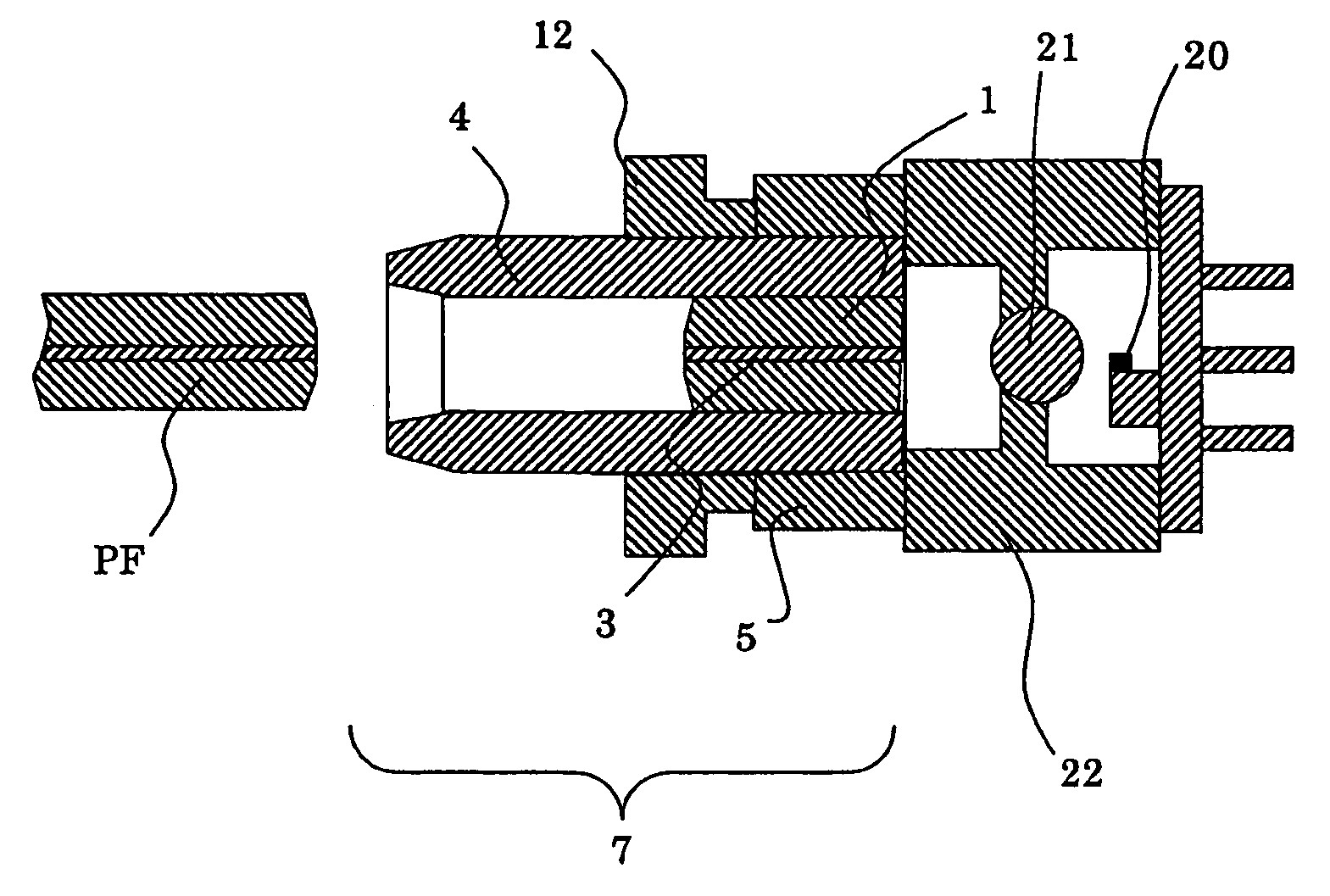
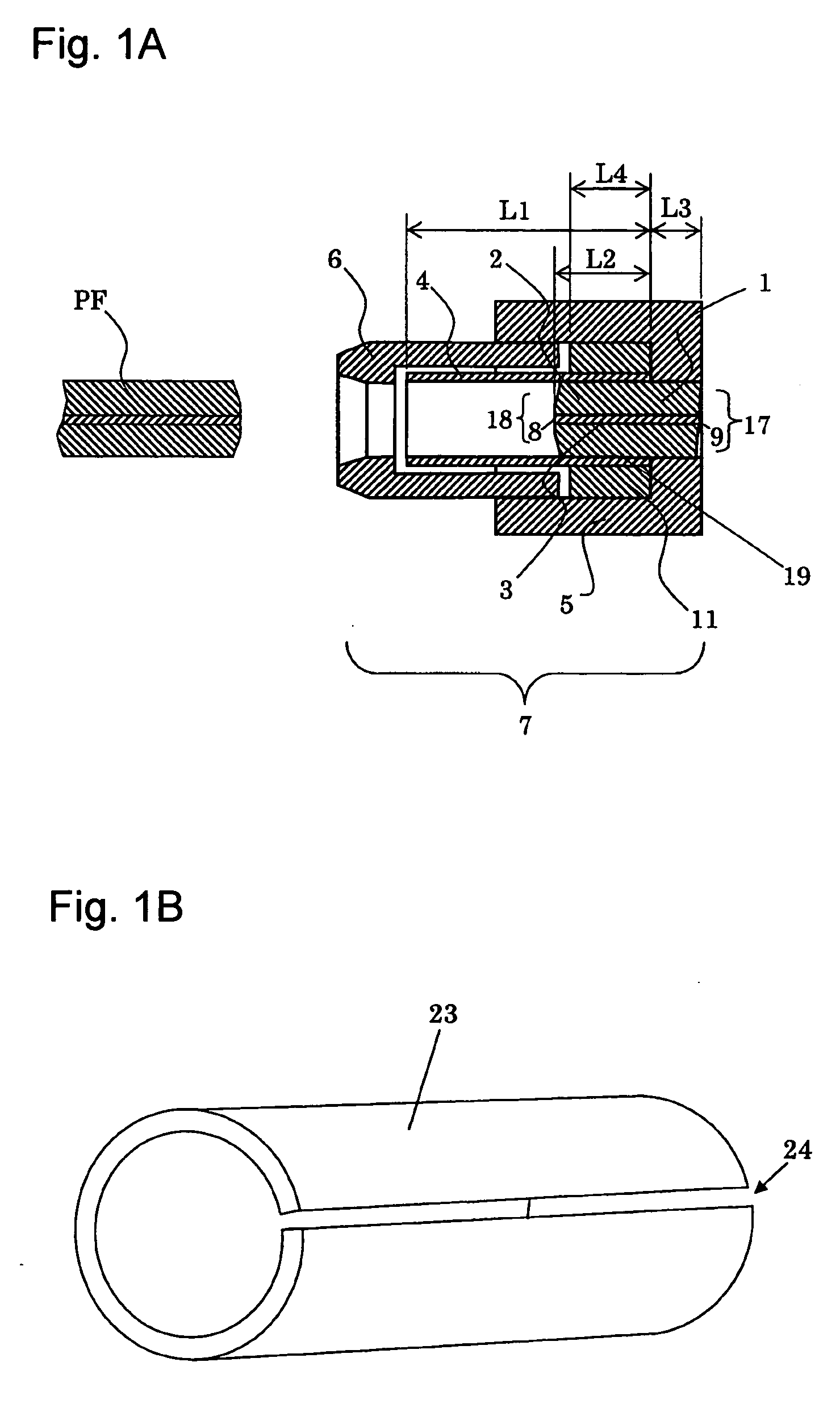
[0058]FIG. 1A is a cross-sectional view showing a first embodiment according to the present invention, including a fiber stub 1 having a ferrule 2 and an optical fiber 3 inserted and fixed in a through-hole of the ferrule 2; a holder 5 to which an rear end 17 of the fiber stub 1 is fixed; a sleeve case 6; and a sleeve 4 for holding a plug ferrule PF connectable with an front end 18 of the fiber stub 1; wherein the sleeve 4 is inserted and held on the front end 18 of the fiber stub 1.
[0059] And then, a resin is filled on an outer side face 19 where the sleeve 4 and the fiber stub 1 are overlapped to each other, thereby forming a grip ring 11 for preventing the sleeve 4 from tilting. And since the grip ring 11 is an elastic body, the sleeve 4 is hardly deformed or tilted.
[0060] Hereinafter, a length L1 of the sleeve 4, an overlapping length L2 of the sleeve 4 and the fiber stub 1, an overlapping length L3 of the holder 5 and the fiber stub 1, and an overlapping length L4 of the fibe...
second embodiment
[0084]FIG. 3 is a cross-sectional view showing a second embodiment according to the present invention, including a fiber stub 1 having a ferrule 2 and an optical fiber 3 inserted and fixed in a through-hole of the ferrule 2; a holder 5 to which an rear end 17 of the fiber stub 1 is fixed; a sleeve case 6; and a sleeve 4 for holding a plug ferrule PF connectable with an front end 18 of the fiber stub 1; wherein the sleeve 4 is inserted and held on the front end 18 of the fiber stub 1.
[0085] In the sleeve 4 used herein, as shown in FIG. 3, the outer face thereof at the end portion on the insertion side of the fiber stub 1 is machined stepwise to have a thicker portion 4a, a thickness of which is larger than a thickness of the portion for holding the plug ferrule PF, thereby enhancing grip force of the thicker portion 4a.
[0086] Further, the thicker portion 4a is preferably 1.5 to 2.5 times as thick as the other portion, because if the thicker portion 4a becomes thinner than above, it...
experiment 1
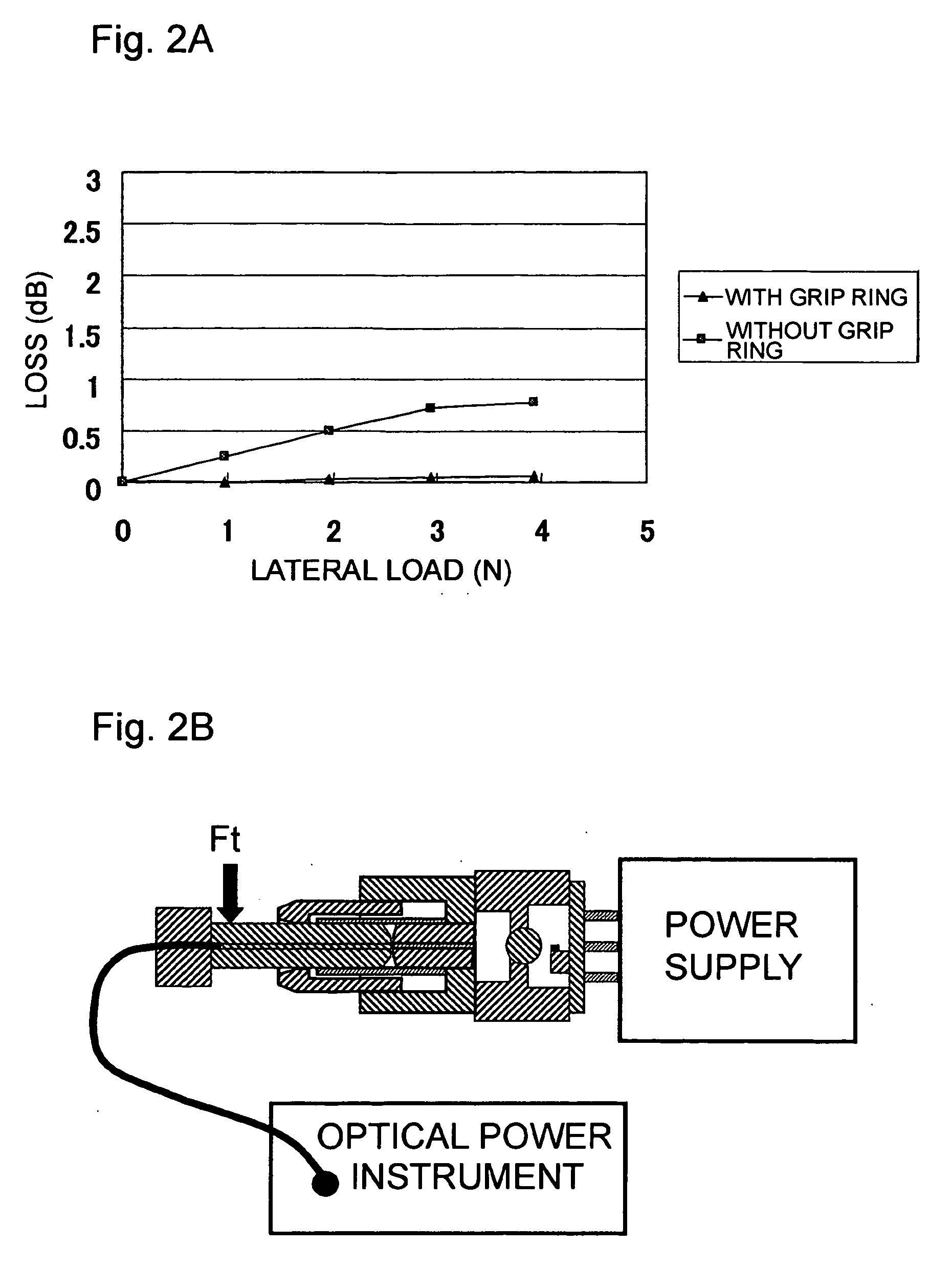
(Experiment 1)
[0102] First, the optical receptacle shown in FIG. 3 for an example and the optical receptacle shown in FIG. 15 for a comparative example were assembled, where an LC connecter was used as an optical connector for the optical receptacle.
[0103] The sleeve for the optical receptacle shown in FIG. 3 was formed so that the thicker portion 4a was 2 times as thick as the other portion, and the length L5 of the thicker portion 4a was ⅓ times as large as the insertion length L2 of the fiber stub l into the sleeve.
[0104] The ferrule used for each fiber stub was made of zirconia ceramics. One ferrule sample with the shape shown in FIG. 3 and another ferrule with the shape shown in FIG. 3 were obtained by extrusion-molding a ceramic molded object in shape of cylinder hollow, followed by sintering and cutting them.
[0105] The optical fiber was inserted and fixed into the through-hole of each of the resulting ferrules, and then the front end was mirror finished to a curved face wi...
PUM
 Abstract
Description
Claims
Application Information