
Method and system for wavelength specific thermal irradiation and treatment

a wavelength-specific thermal irradiation and treatment technology, applied in the field of wavelength-specific thermal irradiation and treatment, can solve the problems of large energy consumption costs, large percentage of the cost of finished articles, and inability to selectively select the existing broad-spectrum infrared sources, so as to reduce the visible clarity and appearance qualities of finished containers, reduce energy consumption costs, and retain the ability to heat efficiently

Active Publication Date: 2006-12-14
PRESSCO IP LLC
View PDF103 Cites 48 Cited by
  • Summary
  • Abstract
  • Description
  • Claims
  • Application Information

AI Technical Summary

Benefits of technology

"The invention provides a system for using infrared radiation for various applications, such as heating materials during manufacturing processes. The system has improved energy conversion efficiency, can be programmed for different materials and targets, and can be pulsed for discrete parts. The system also includes highly directable infrared elements and can be used with preform temperature measurement systems. The invention can provide powerful and highly programmable infrared heating without compromising the appearance of the finished container. The system can also facilitate fast, high-intensity burst pulses and can be packaged in high density for practical use."

Problems solved by technology

It is, therefore, not possible with the existing broad spectrum infrared sources to be selective as to the preferred wavelength or wavelengths that would be the most desired for any given heating, processing or treatment application.
Thus, much of the broadband IR energy output is wasted.
Energy consumption costs make up a large percentage of the cost of a finished article that is manufactured using blow molding operations.
Convection heating of the preforms caused by hot air flow has proven to result in non-uniform heating of the preforms and, thus, has a deleterious effect on the manufacturing operation.
As might be expected, the transfer of thermal energy from historical state-of-the-art IR heating elements and systems to the targeted preforms is not a completely efficient process.
More specifically, if a fixed amount of input energy is continuously consumed by a stationary IR heating element, even at times when there are no preforms in the immediate vicinity of the heater due to continuous preform movement through the system, the energy conversion efficiency performance of the systems is obviously not optimized.
Beyond this wavelength, any energy emitted by the enclosed filament is, for the most part, absorbed by the quartz glass sheath that encloses the filament and is therefore not directly available for preform heating.
While being a viable means of increasing the overall energy conversion efficiency performance of the reheat process, the change in the absorption property of the preforms that is so beneficial in reducing the manufacturing costs of the container also has a deleterious effect on the appearance of the finished container.
In this patent, the independent operation of an injection molding machine and a blow molding machine, each adding a significant amount of energy into the process of thermally conditioning the thermoplastic material, is described as wasteful.
More specifically, in a one-stage process as described in the '039 patent, the preform is not allowed to stabilize to room temperature after the injection molding process.
Though the operation of single-stage injection molding / blow molding machines are known in the art, finished container quality problems persist for these machines.
These quality problems are linked to preform-to-preform temperature variations as the stream of preforms enters the blowing stage.
Despite the advances described in the '039 patent, using heretofore state-of-the-art IR heating and temperature sensing means and methods, the process of thermally conditioning preforms shortly after they have been removed from an injection molding process still results in preforms of varying thermal content entering the blowing stage.
Inefficiencies in the ability to custom tune the IR heating process on a preform-to-preform basis results in manufacturers opting to use a reheat blow molding method to achieve required quality levels.
Though several attempts have been made to render improvements in the state-of-the-art IR heating subsystems, clear deficiencies still persist.

Method used


Image

  • Method and system for wavelength specific thermal irradiation and treatment
  • Method and system for wavelength specific thermal irradiation and treatment
  • Method and system for wavelength specific thermal irradiation and treatment

Examples


Embodiment Construction

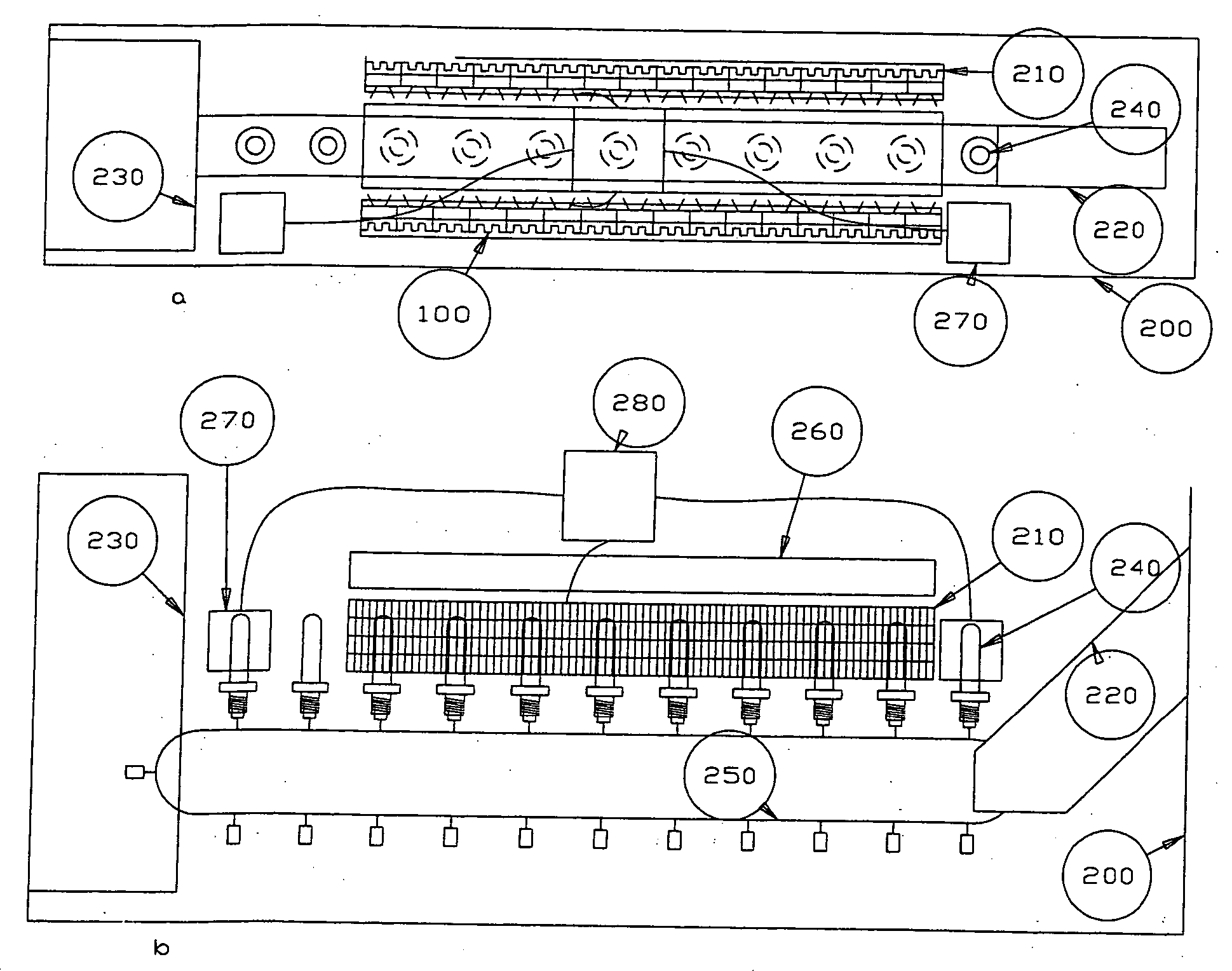
[0058] The benefits of providing wavelength specific irradiation can be illustrated by looking at a hypothetical radiant heating example. Assume that a material which is generally transparent to electromagnetic radiation from the visible range through the mid-infrared range requires process heating to support some manufacturing operation. Also assume that this generally transparent material has a narrow but significant molecular absorption band positioned between 3.0 and 3.25 micrometers. The example described above is representative of how the presently described embodiments might be most advantageously applied within industry. If the parameters of this particular process heating application dictated the use of radiant heating techniques, the current state-of-the-art would call for the use of quartz lamps operated at a filament temperature of approximately 3000° K. At this filament temperature, fundamental physical calculations yield the result that only approximately 2.1% of the t...


PUM

PropertyMeasurementUnit
wavelengthaaaaaaaaaa

Abstract

A system for direct injection of selected thermal-infrared (IR) wavelength radiation or energy into articles for a wide range of processing purposes is provided. These purposes may include heating, raising or maintaining the temperature of articles, or stimulating a target item in a range of different industrial, medical, consumer, or commercial circumstances. The system is especially applicable to operations that require or benefit from the ability to irradiate at specifically selected wavelengths or to pulse or inject the radiation. The system is particularly advantageous when functioning at higher speeds and in a non-contact environment with the target.

Description

BACKGROUND OF THE INVENTION [0001] This invention relates to the direct injection of selected thermal-infrared (IR) wavelength radiation or energy into targeted entities for a wide range of heating, processing, or treatment purposes. As will be described below, these purposes may include heating, raising or maintaining the temperature of articles, or stimulating a target item in a range of different industrial, medical, consumer, or commercial circumstances. The methods and system described herein are especially applicable to operations that require or benefit from the ability to irradiate at specifically selected wavelengths or to pulse or inject the radiation. The invention is particularly advantageous when the target is moving at higher speeds and in a non-contact environment with the target. The invention provides for an infrared system of selected narrow wavelengths which is highly programmable for a wide range of end applications. The invention teaches a new and novel type of ...

Claims


Application Information

Patent Timeline
Patent Type & Authority Applications(United States)
IPC IPC(8): B29C35/08A23L5/10A23L5/30H01L33/00H01L33/08H01L33/12H01L33/30
CPCB29B13/023B29B13/024H01L2224/48091B29B2911/1402B29B2911/14026B29B2911/14033B29B2911/1404B29B2911/14106B29B2911/14133B29B2911/14213B29C35/08B29C49/06B29C49/64B29C49/78B29C2035/0822H05B3/0057A23L3/005A23L3/26A23L1/0128A23L1/0257H01L2924/00014A23L5/36A23L5/15H01L2224/45139Y02P60/85B29C2949/26B29C2949/28B29C2949/24B29C2949/22B29C2949/3024B29C2949/3032B29C2949/3056B29C2949/0715B29C2049/78675H01L2924/00011H01L2224/45015H01L2924/207B29C49/68H01L2924/00
Inventor COCHRAN, DON W.CECH, STEVEN D.MORGAN, NOEL EDWARD
Owner PRESSCO IP LLC
Learn More