[0022] In accordance with the invention, super-resolution recording and super-resolution
reproduction can be performed at a λ / NA setting of 640 nm or below by use of a laser beam with a wavelength (λ) shorter than about 635 nm and an objective lens with a
numerical aperture greater than about 0.6. Moreover, the main component in the light
absorption layer is the foregoing material, so that the
noble metal oxide layer has no inhibition in becoming locally deformed at the time of recording and it becomes possible to acquire excellent
signal characteristics even when minute recording marks are formed.
[0023] In addition, it is preferable that
platinum oxide (PtOx) is contained in the
noble metal oxide layer. In this case, it is especially preferable that the noble
metal oxide layer is constituted substantially of
platinum oxide (PtOx), but there's nothing wrong with containing therein other components and inevitably mixed impurities. The use of
platinum oxide (PtOx) as an component in the noble
metal oxide layer makes it possible to obtain excellent
signal characteristics and sufficient durability.
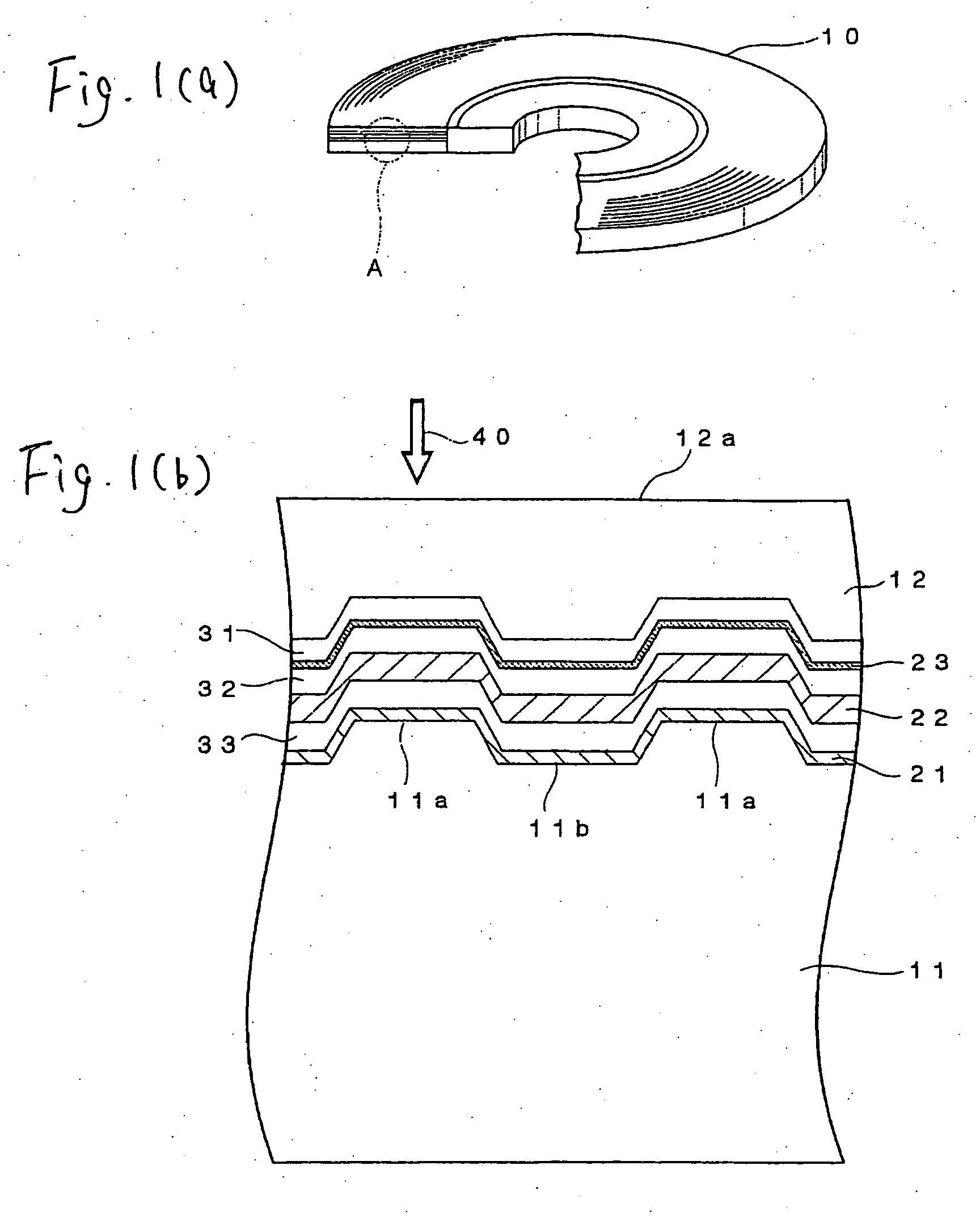
[0024] It is also preferable that the optical recording medium according to the invention further has a
reflective layer provided between the supporting substrate and the third
dielectric layer. By providing such a
reflective layer, the level of
reproduction signals is heightened and the reproduction stability is substantially enhanced as well. The term “reproduction stability” as used herein refers to the resistance to a deterioration phenomenon caused by reproduction, namely a phenomenon that the noble
metal oxide layer changes its state by energy of a laser beam applied thereto at the time of reproduction and thereby a
noise increase and a carrier decrease is caused to result in CNR reduction. The thickness of the
reflective layer is preferably from 5 nm to 200 nm, far preferably from 10 nm to 100 nm, particularly preferably from 10 nm to 50 nm. By setting the reflective
layer thickness at such a value, it becomes possible to achieve a sufficient reproduction stability enhancement effect without a big drop in productivity.
[0027] In accordance with the invention, it becomes possible to manufacture optical recording media which enable super-resolution recording and super-resolution reproduction to be performed at a λ / NA setting of 640 nm or below by use of a laser beam with a wavelength (λ) shorter than about 635 nm and an objective lens with a numerical aperture greater than about 0.6. Moreover, since the main component in the light absorption layer is the foregoing material, excellent signal characteristics can be obtained even when minute recording marks are formed. Moreover, since the main component in the light absorption layer is the foregoing material, excellent signal characteristics can be obtained even when minute recording marks are formed. It is preferable that the first process is carried out according to a vapor deposition method and the second process is carried out according to a
spin coating method.
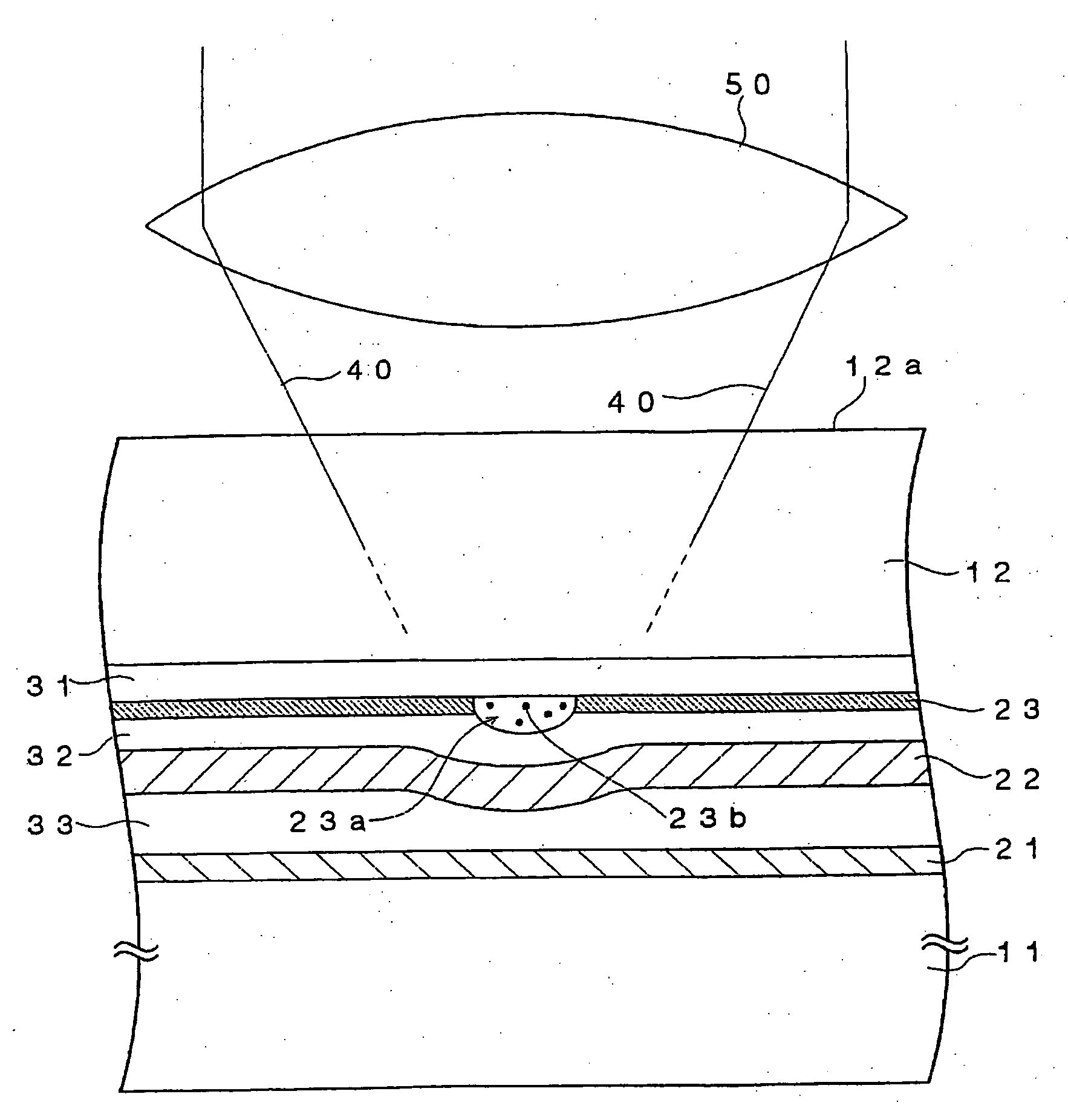
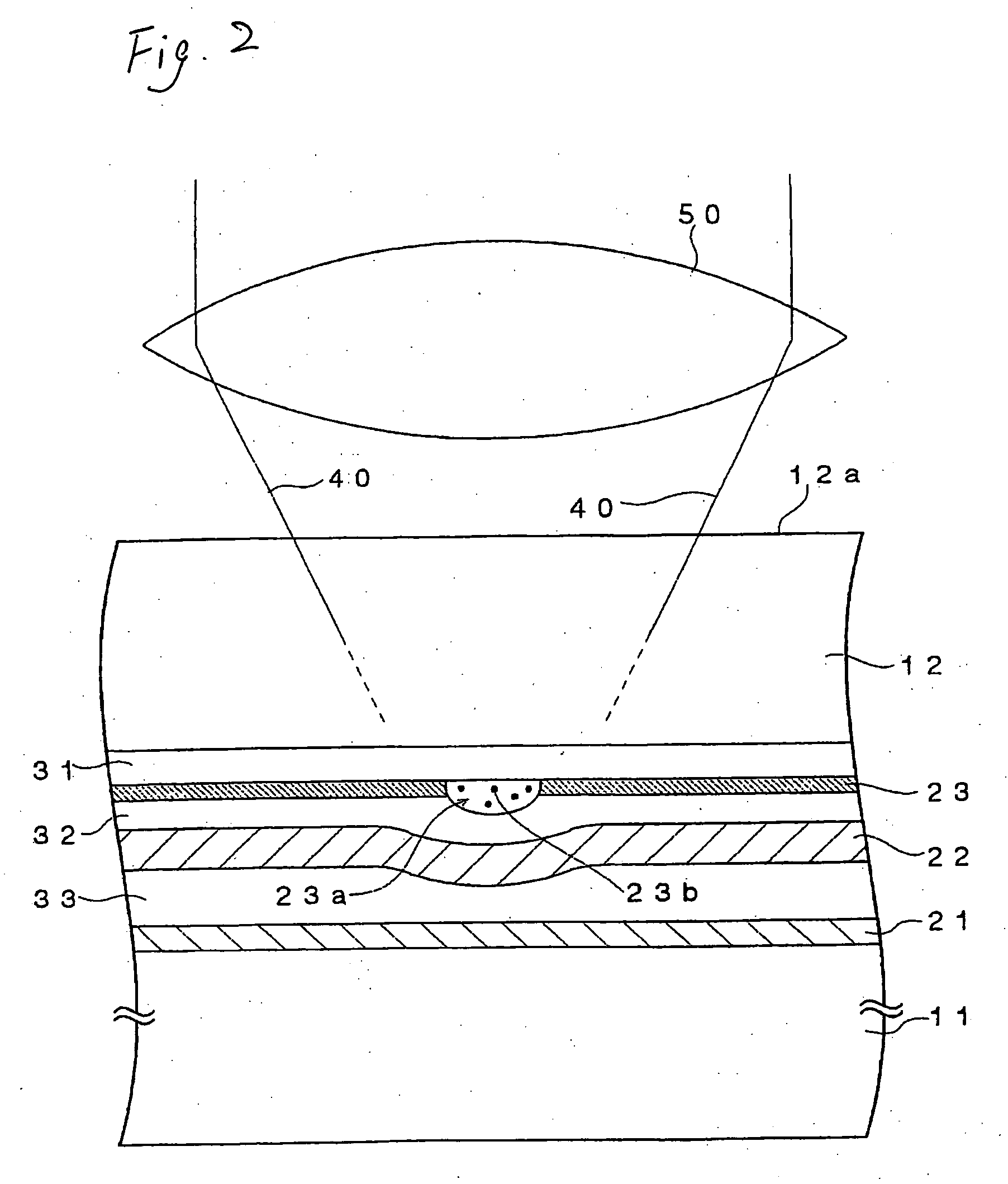
[0028] The
data recording method according to the invention is a
data recording method in which data is recorded by a laser beam being applied to the foregoing optical recording medium from the light absorption layer side, and is characterized in that, when the wavelength of the foregoing laser beam is represented as λ and the numerical aperture of the objective lens for focusing the laser beam is represented as NA, the λ / NA value is set at 640 nm or below and a recording mark
train including recording marks λ / 4NA or below in length is recorded. On the other hand, the data reproducing method according to the invention is a data reproducing method in which data is reproduced by a laser beam being applied to the foregoing optical recording medium from the light-transmitting layer side, and is characterized in that, when the wavelength of the foregoing laser beam is represented as λ and the numerical aperture of the objective lens for focusing the laser beam is represented as NA, the λ / NA value is set at 640 nm or below and the data is reproduced from a
train of recorded marks including the recorded marks λ / 4NA or below in length. In both cases, it is most favorable that the wavelength of the laser beam used is set at about 405 nm and the numerical aperture of the objective lens used is set at about 0.85. By doing so, the same recording-and-reproducing apparatus as used for next-generation optical recording media can be utilized, so the costs for development and production of recording-and-reproducing apparatus can be reduced.
[0029] In accordance with the invention, super-resolution recording and super-resolution reproduction can be performed at a λ / NA setting of 640 nm or below by use of a laser beam with a wavelength shorter than about 635 nm and an objective lens with a numerical aperture greater than about 0.6, and it becomes possible to obtain excellent characteristics in super-resolution recording and super-resolution reproduction, notably those using a laser beam with a wavelength shorter than about 405 nm and an objective lens with a numerical aperture greater than about 0.85 which are those used for next-generation optical recording media. Accordingly, the same recording-and-reproducing apparatus as used for next-generation optical recording media can be utilized, so the costs for development and production of recording-and-reproducing apparatus can be reduced.

