Semiconductor device and manufacturing method of the same
- Summary
- Abstract
- Description
- Claims
- Application Information
AI Technical Summary
Benefits of technology
Problems solved by technology
Method used
Image
Examples
embodiment 1
[0084] At first, the cause for the degradation of the TDDB life between a buried interconnection using the copper as the main conductor layer described above by the present inventors is to be explained. The TDDB (Time Dependence on Dielectric Breakdown) life is a measure for objectively determining the time dependence of dielectric breakdown, which is a time (life) obtained by applying a relatively high voltage between electrodes under a measuring condition at a predetermined temperature (for example, 140° C.), preparing a graph by plotting a time from voltage application to dielectric breakdown relative to the applied electric field and extrapolating to an electric field intensity actually used (for example, 0.2 MV / cm) in view of the graph.
[0085] Degradation of the TDDB life is generally considered to be attributable to that copper applied to the interconnection material diffuses to the periphery, and lowers the dielectric breakdown voltage between interconnections. However, accor...
embodiment 2
[0143]FIG. 31 is a cross sectional view for a main portion in the manufacturing step of a semiconductor device as other embodiment of the invention. The semiconductor device of this embodiment has a multi-layered interconnection structure having, in combination, a structure with an air gap being formed between adjacent interconnections and having an interconnection layer not connecting adjacent interconnections with a CMP surface and having a reservoir as in the second layer interconnection layer 26 and the third layer interconnection 47 of the embodiment 1 and an interconnection layer formed by using a general embedding interconnection technique. In FIG. 31, since the steps up to the formation of the insulative film 60 above the fourth layer interconnection 55 are substantially identical with the manufacturing steps of FIG. 4 to FIG. 10 and FIG. 18 to FIG. 30 of the embodiment 1, explanation therefor is omitted and only the subsequent manufacturing steps are to be described herein....
embodiment 3
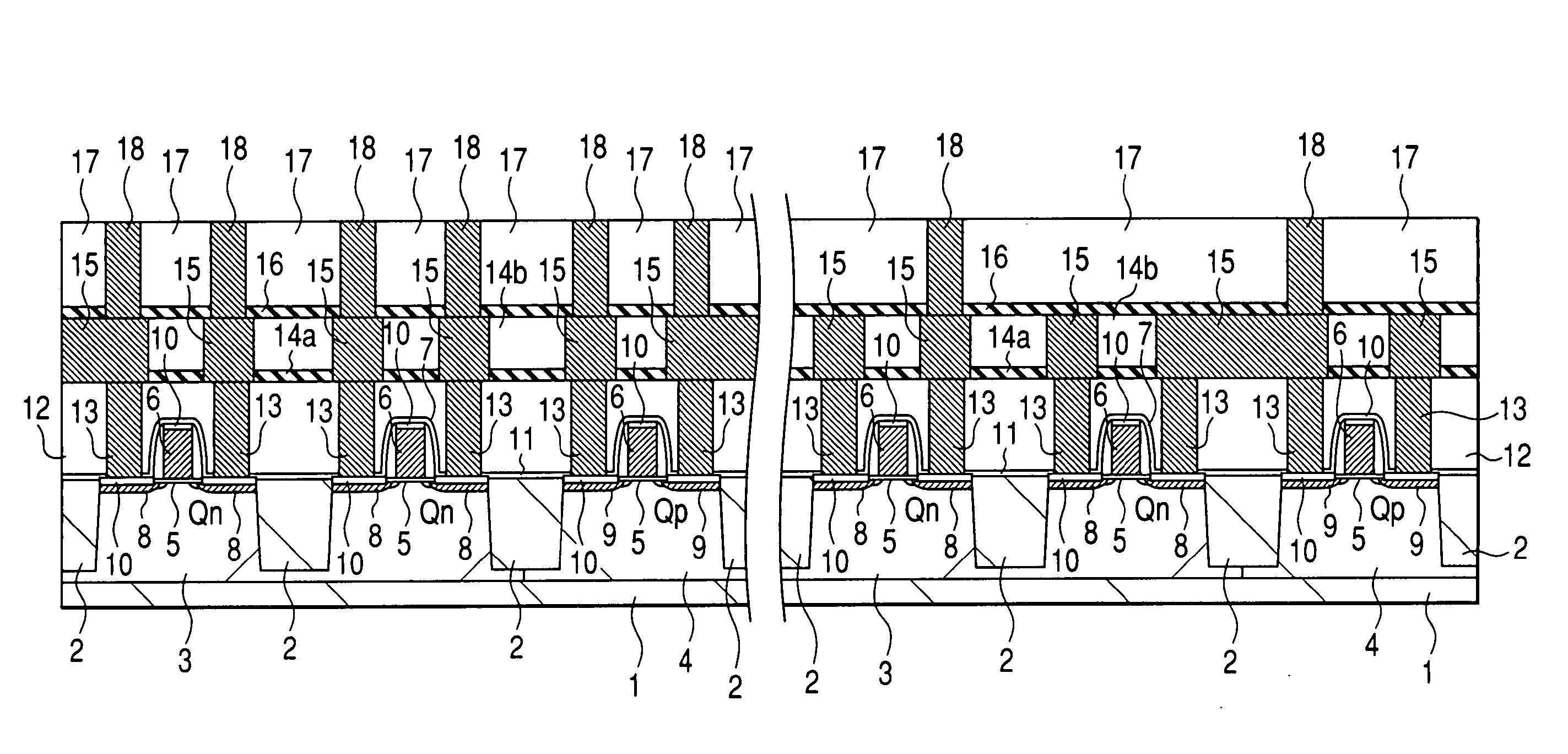
[0147]FIG. 32 is a cross sectional view for a main portion in the manufacturing step of a semiconductor device as other embodiment of the invention succeeding to FIG. 3. Also in FIG. 32, those portions corresponding to the structure below the insulative film 17 in FIG. 3 are not illustrated in the drawing.
[0148] This embodiment shows an air gap-interconnection in a case of forming an interconnection layer from a conductive film typically represented by an aluminum (Al) interconnection by a dry etching method.
[0149] At first in this embodiment, as shown in FIG. 32, a conductive film 70 is formed over an insulative film 17 in which a through hole 18 is buried by a sputtering method or a CVD method. The conductive film 70 referred to herein is not restricted only to aluminum but may be changed variously. For example, it may also be a single film formed, for example, of aluminum (Al) or aluminum alloy, or a laminate metal film in which a metal film such as of titanium (Ti) or titanium...
PUM
 Abstract
Description
Claims
Application Information
 - R&D
- Intellectual Property
- Life Sciences
- Materials
- Tech Scout
- Unparalleled Data Quality
- Higher Quality Content
- 60% Fewer Hallucinations
Browse by: Latest US Patents, China's latest patents, Technical Efficacy Thesaurus, Application Domain, Technology Topic, Popular Technical Reports.
© 2025 PatSnap. All rights reserved.Legal|Privacy policy|Modern Slavery Act Transparency Statement|Sitemap|About US| Contact US: help@patsnap.com


