Combined radio frequency and hall effect ion source and plasma accelerator system

a plasma accelerator and radio frequency technology, applied in nuclear engineering, machines/engines, instruments, etc., can solve the problems of reducing the efficiency of the system, and reducing the efficiency of the hall effect ion source and plasma accelerator system,

Active Publication Date: 2006-12-21
BUSEK
View PDF8 Cites 65 Cited by
  • Summary
  • Abstract
  • Description
  • Claims
  • Application Information

AI Technical Summary

Benefits of technology

[0009] It is a further object of this invention to provide such a system which improves efficiency.
[0010] It is a further object of this invention to provide such a system which eliminates the need to depend on the DC voltage for ionization.
[0013] It is a further object of this invention to provide such a system which can tune the ion energy level of ions while maintaining a constant high ion flux density.
[0016] It is a further object of this invention to provide such a system which increases the maximum specific impulse.
[0017] It is a further object of this invention to provide such a system which increases the available thrust to power ratio at lower DC voltages.
[0018] It is a further object of this invention to provide such a system which efficiently ionizes a gas to create plasma.

Problems solved by technology

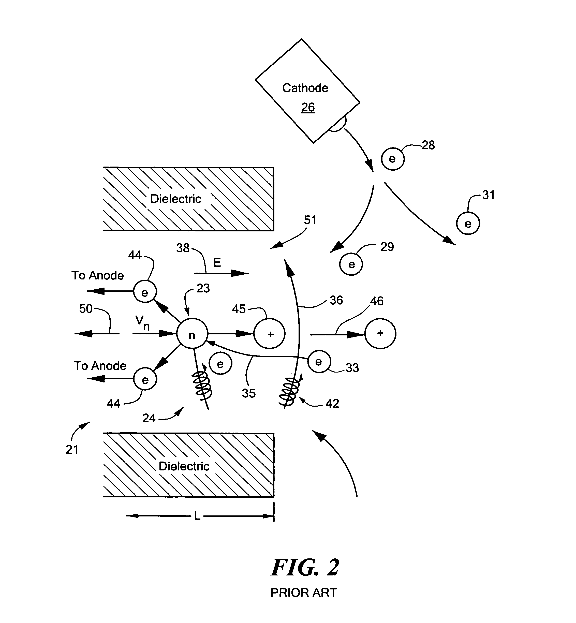
The result is ionization and acceleration are closely coupled causing the system to have a smaller operating envelope and lower efficiency than may be possible if the processes could be separated.
Therefore, conventional Hall Effect ion source and plasma accelerator systems are unable to efficiently generate ion flux with ions having low (e.g., <10 eV) or mid ion energy (e.g., <130 eV) levels while maintaining a constant high ion flux density.
Conventional Hall Effect ion source systems are also limited by the maximum DC voltage that can be utilized because arcs are typically generated in the discharge region of the plasma accelerator at high DC voltages, typically greater than about 1,000 V. This limits the maximum DC voltage that can be employed and therefore the maximum specific impulse that can be achieved.

Method used


Image

  • Combined radio frequency and hall effect ion source and plasma accelerator system
  • Combined radio frequency and hall effect ion source and plasma accelerator system
  • Combined radio frequency and hall effect ion source and plasma accelerator system

Examples


Embodiment Construction

[0031] Aside from the preferred embodiment or embodiments disclosed below, this invention is capable of other embodiments and of being practiced or being carried out in various ways. Thus, it is to be understood that the invention is not limited in its application to the details of construction and the arrangements of components set forth in the following description or illustrated in the drawings. If only one embodiment is described herein, the claims hereof are not to be limited to that embodiment. Moreover, the claims hereof are not to be read restrictively unless there is clear and convincing evidence manifesting a certain exclusion, restriction, or disclaimer.

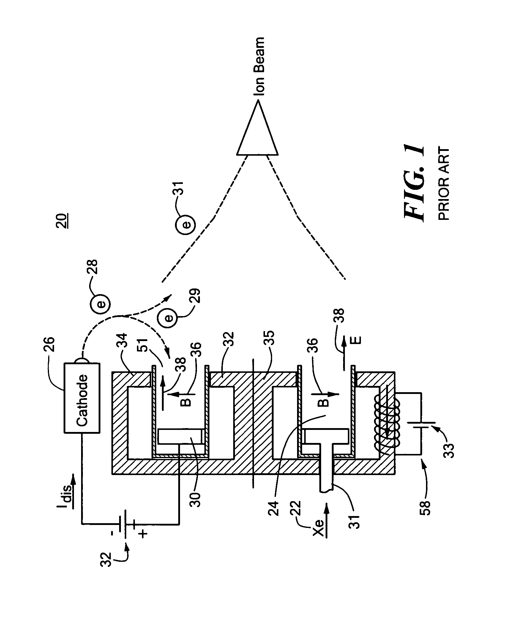
[0032] Conventional Hall Effect ion source and plasma accelerator system 20, FIG. 1, includes plasma accelerator 21 with discharge chamber 24, anode 30 and propellant or gas distributor 31 in discharge chamber 24 with transverse magnetic field (B) 36 and axial electric field (E) 38. Propellant 22, e.g., xenon or other gas...


PUM

PropertyMeasurementUnit
DC voltagesaaaaaaaaaa
DC voltageaaaaaaaaaa
frequencyaaaaaaaaaa

Abstract

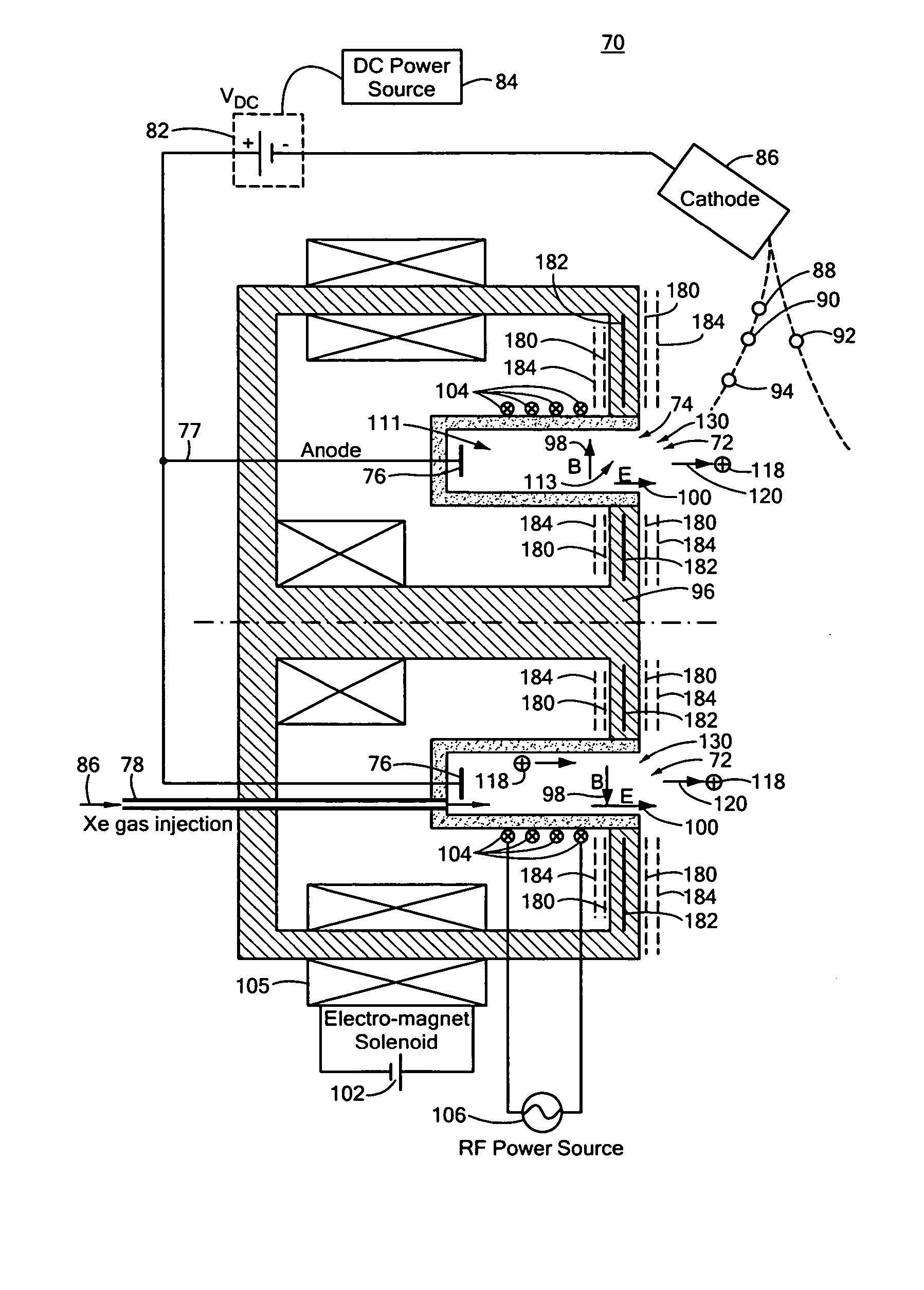
This invention features a combined radio frequency (RF) and Hall Effect ion source and plasma accelerator system including a plasma accelerator having an anode and a discharge zone, the plasma accelerator for providing plasma discharge. A gas distributor introduces a gas into the plasma accelerator. A cathode emits electrons attracted to the anode for ionizing the gas and neutralizing ion flux emitted from the plasma accelerator. An electrical circuit coupled between the anode and the cathode having a DC power source provides DC voltage. A magnetic circuit structure including a magnetic field source establishes a transverse magnetic field in the plasma accelerator that creates an impedance to the flow of the electrons toward the anode to enhance ionization of the gas to create plasma and which in combination with the electric circuit establishes an axial electric field in the plasma accelerator. An RF power source provides RF power to at least one electrode disposed about and / or inside the plasma accelerator that induces current for ionizing the gas to create the plasma such that the axial electric field accelerates ions through the plasma accelerator to provide ion flux.

Description

RELATED APPLICATIONS [0001] This application claims benefit of and priority to U.S. Provisional Application Ser. No. 60 / 675,426 filed Apr. 27, 2005, incorporated by reference herein.FIELD OF THE INVENTION [0002] This invention relates to a combined radio frequency (RF) and Hall Effect ion source and plasma accelerator system. BACKGROUND OF THE INVENTION [0003] Conventional Hall Effect ion source and plasma systems typically include a plasma accelerator, a gas distributor for introducing a gas into the plasma accelerator, and an anode located at one end of a channel. A DC voltage provided by a DC power source connected to an electric circuit creates an electric potential between the anode and a floating externally located cathode that emits electrons. A magnetic circuit structure with a magnetic field source, e.g., one or more permanent magnet or electromagnetic coil, creates a transverse magnetic field. The electric circuit and the magnetic circuit structure establish an axial elect...

Claims


Application Information

Patent Timeline
Patent Type & Authority Applications(United States)
IPC IPC(8): H01J7/24
CPCF03H1/0075H05H1/54H01J27/16H01J27/143
Inventor HRUBY, VLADIMIRHOHMAN, KURTBROGAN, THOMAS
Owner BUSEK
Why Eureka
Try Eureka