Composite distributed dielectric structure

a dielectric structure and distributed dielectric technology, applied in the field of dielectric structures, can solve the problems of increasing cross-talk, dielectric loss, propagation delay at high frequency transmission, propagation delay, and signal wavelength becoming shorter, so as to maintain proper heat dissipation and noise reduction, reduce dielectric loss, cross-talk and signal propagation delay.

Inactive Publication Date: 2006-12-21
IND TECH RES INST
View PDF8 Cites 14 Cited by
  • Summary
  • Abstract
  • Description
  • Claims
  • Application Information

AI Technical Summary

Benefits of technology

[0018] The fundamental structures provided in this invention can be used for high-speed connectors, high-speed cables, and intra-chip and inter-chip interconnects systems at high speed transmission. The present invention provides a low cost and prac...

Problems solved by technology

However, signal lines surrounded by high dielectric constant materials can cause an increase of cross-talk, dielectric loss, and propagation delay at high frequency transmission.
The propagation delay is due to the fact that the wavelength of a signal becomes shorter when it propagates through a material with a higher dielectric constant
In general, low dielectric constant materials are adopted for high speed and low loss transmission of signals but their poor heat dissipative ca...

Method used


Image

  • Composite distributed dielectric structure
  • Composite distributed dielectric structure
  • Composite distributed dielectric structure

Examples


Embodiment Construction

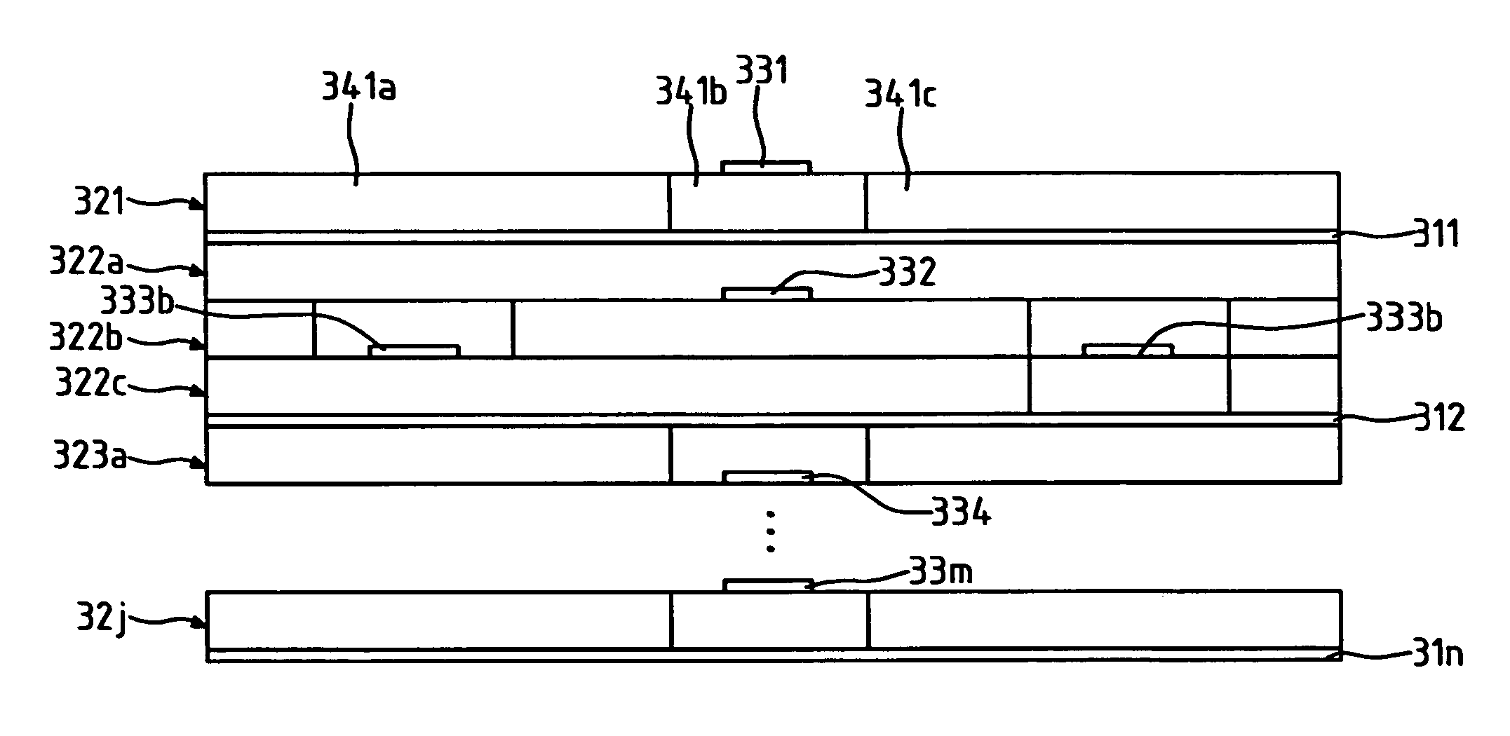
[0034] In the invention, a composite distributed dielectric structure having different dielectric constants is provided to meet specific requirements in high frequency electronic circuits. Both high- and low-dielectric constants materials are chosen in different areas of a circuit board or substrate to meet specific applications. FIG. 3A is a diagram of the composite distributed dielectric structure in a first preferred embodiment according to the present invention.

[0035] The composite distributed dielectric structure of FIG. 3A comprises one or more conductor layers, one or more dielectric layers distributed on the conductor layers, and one or more conductor traces distributed on the dielectric layers. At least one dielectric layer has plural dielectric materials therein.

[0036] Referring to FIG. 3A, the composite distributed dielectric structure 300 comprises conductor layers 311-31n, dielectric layers 321, 322a-322c, 323a, . . . , 32j formed on the conductor layers 311-31n, and ...


PUM


Abstract

This invention discloses a composite distributed dielectric structure. It comprises one or more conductor layers, one or more dielectric layers distributed on the conductor layers, and one or more conductor traces distributed on the dielectric layers. One or more dielectric plates can be further around the conductor traces. The dielectric layers or plates may or may not have plural dielectric materials therein, respectively described in two embodiments. Each conductor trace lies on a dielectric material without crossing two different dielectric materials. Two or more dielectric layers may be stacked on the conductor layers The invention provides a low cost and practical dielectric structure for interconnect systems to reduce dielectric loss, cross talk, and signal propagation delay and to well control the impedance matching while maintaining proper heat dissipation and noise reduction at high frequency transmission.

Description

FIELD OF THE INVENTION [0001] The present invention generally relates to dielectric structures used for interconnects systems, and more specifically to a composite distributed dielectric structure. It is applicable to interconnects systems at high-speed circuits. BACKGROUND OF THE INVENTION [0002] The growing trend of more functionality and smaller form factor for electronic components has resulted in a dramatic increase of electrical interconnect density in integrated circuits (intra-chip interconnect), electronic packages and circuit boards (inter-chip interconnect). Dielectric layers in electronic circuits are employed as capacitors or circuit boards / substrates. High dielectric constant materials normally have better heat dissipative capability than the low dielectric constant materials, and therefore make them ideal for power components at high frequencies, such as microwave frequencies. A high dielectric constant material also leads to a large interconnect capacitance, which ha...

Claims


Application Information

Patent Timeline
IPC IPC(8): H01G4/20
CPCH01L23/49822H01L2924/3011H01P3/081H01P3/085H05K1/024H05K1/0298H05K3/386H01L2924/0002H05K2201/0187H05K2201/0195H05K2201/09881H01L2924/00
Inventor CHANG, CHIH-HAOWU, SHIH-HSIENLEE, MIN-LINLAY, SHINN-JUH
Owner IND TECH RES INST
Why Eureka
Try Eureka