Exhaust gas purifier

a technology of exhaust gas and purifier, which is applied in the direction of electric control, machines/engines, separation processes, etc., can solve the problems of insufficient exhaust emission control effect, insufficient work of post-processing devices, and rare chance for exhaust gas from diesel engines in normal operating status to reach a temperature level, etc., to suppress the runup of fuel cost, reduce the effect of exhaust gas passing through the oxidation catalyst and increasing the temperature of the exhaust gas

a technology of exhaust gas and purifier, which is applied in the direction of electric control, machines/engines, separation processes, etc., can solve the problems of insufficient exhaust emission control effect, insufficient work of post-processing devices, and rare chance for exhaust gas from diesel engines in normal operating status to reach a temperature level, etc., to suppress the runup of fuel cost, reduce the effect of exhaust gas passing through the oxidation catalyst and increasing the temperature of the exhaust gas

US20060288689A1Inactive Publication Date: 2006-12-28HINO MOTORS LTD

Image

  • Exhaust gas purifier
  • Exhaust gas purifier
  • Exhaust gas purifier

Examples


Embodiment Construction

[0042] Embodiments of the invention will be described with reference to the drawings.

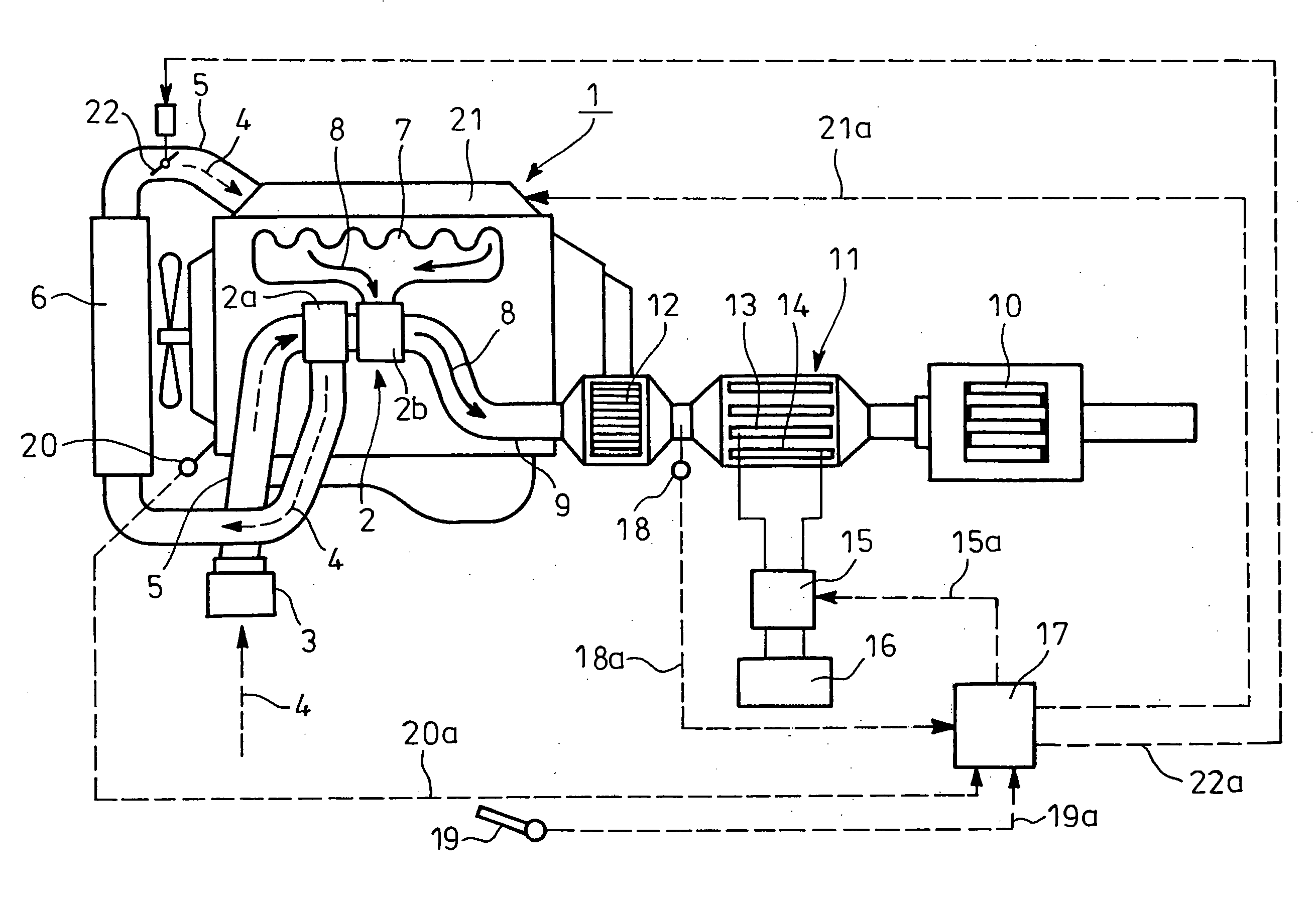
[0043] FIGS. 1 to 3 show an embodiment of the invention. In FIG. 1, reference numeral 1 designates a diesel engine (internal combustion engine) with a turbocharger 2. Suction air 4 sucked through an air cleaner 3 is guided via a suction pipe 5 to a compressor 2a of the turbocharger 2 so as to compress the same, the compressed suction air 4 being passed through an intercooler 6 and being distributed to respective cylinders of the diesel engine 1.

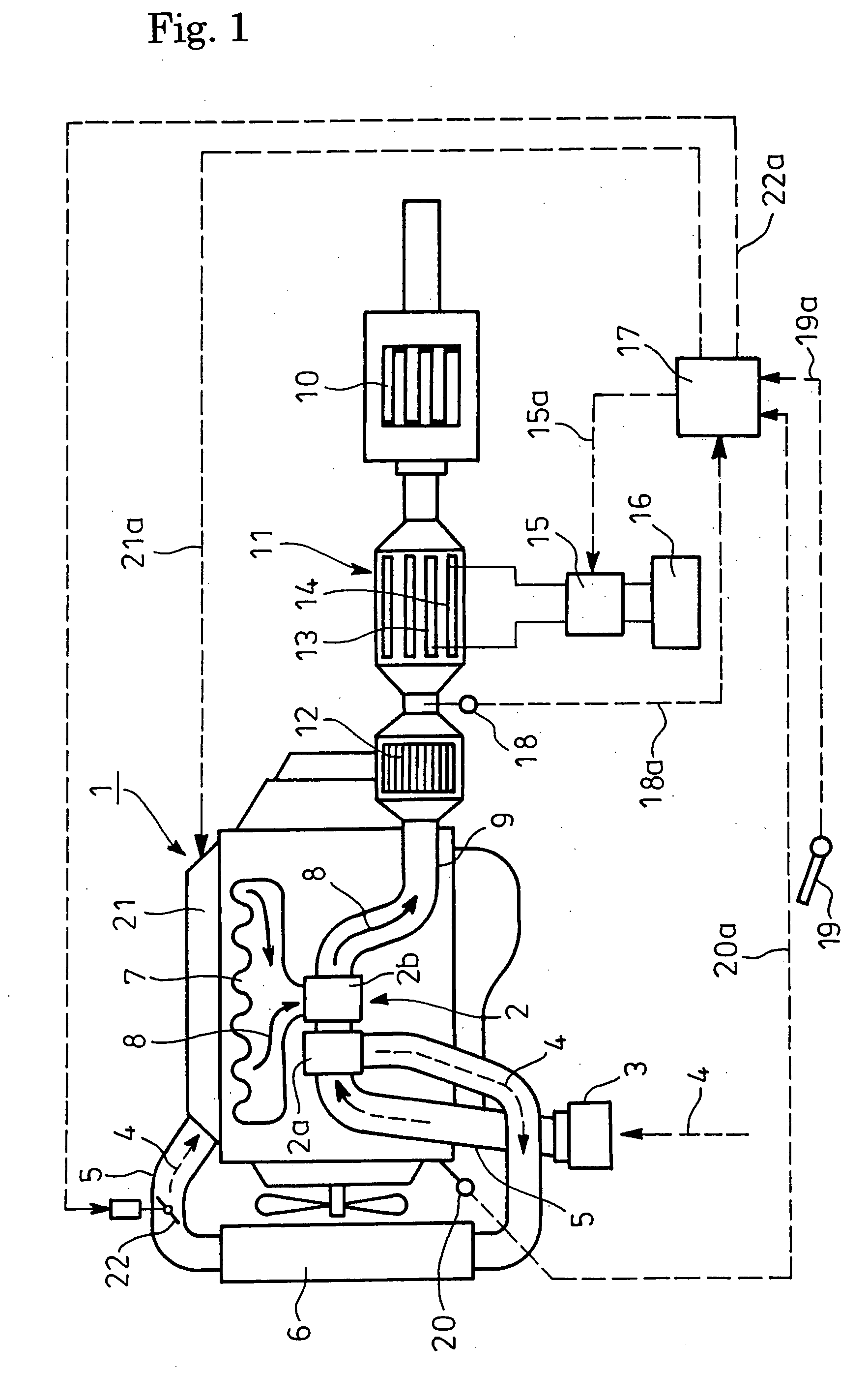
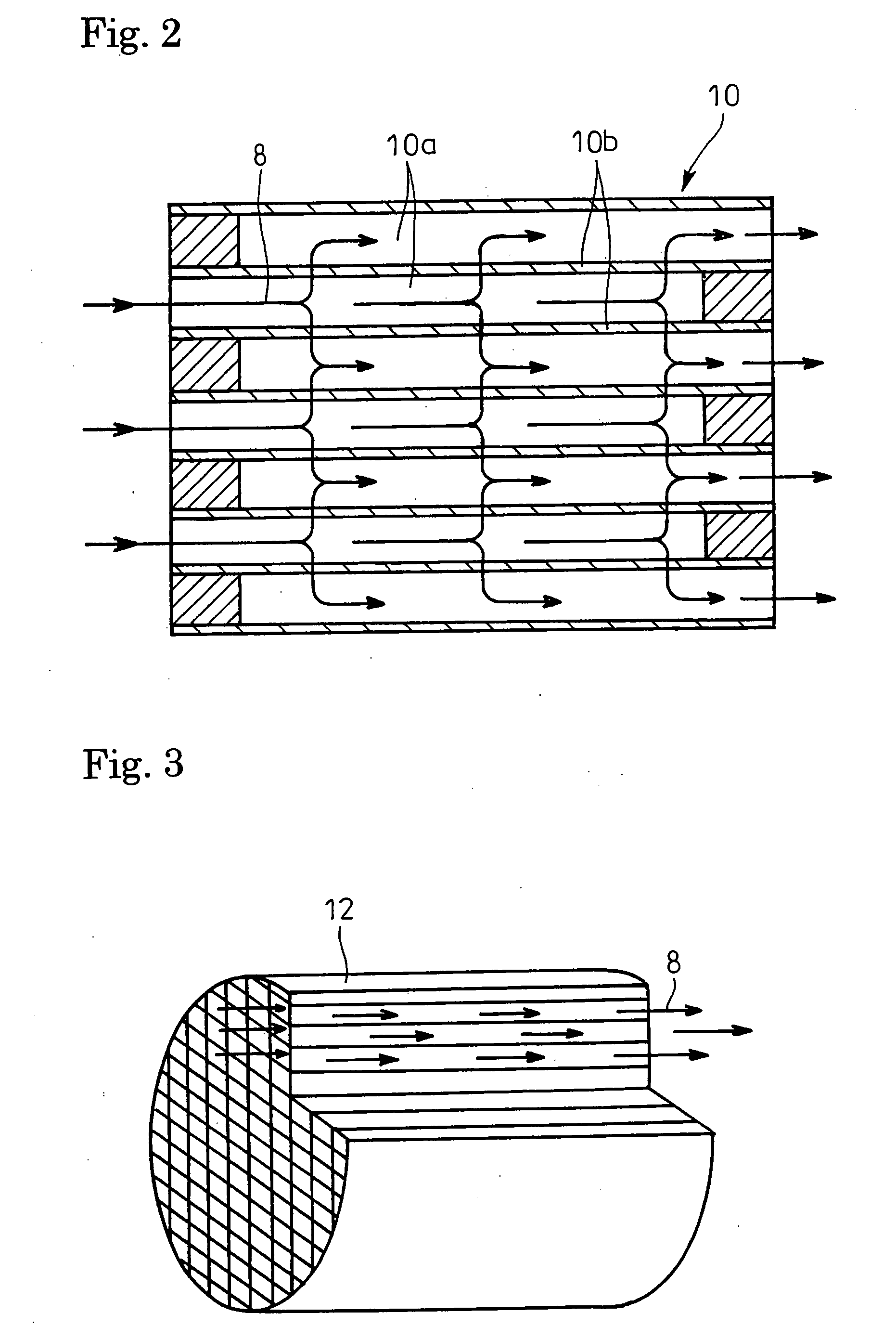
[0044] Exhaust gas 8 discharged via an exhaust manifold 7 from the respective cylinders of the diesel engine 1 is fed to a turbine 2b of the turbocharger 2; the exhaust gas 8 having driven the turbine 2b is passed through a catalyst regenerative particulate filter 10 (post-processing device) for capturing of particulates and is discharged.

[0045] As shown in FIG. 2 in an enlarged scale, the particulate filter 10 is a porous honeycomb structure made of ceram...


PUM

PropertyMeasurementUnit
crank angleaaaaaaaaaa
exhaust temperatureaaaaaaaaaa

Abstract

Provided is an exhaust emission control device which can properly burn off soot and soluble organic fraction attached to and accumulated on electrodes of a plasma generator. The exhaust emission control device with a post-processing device (catalyst regenerative particulate filter 10) for allowing exhaust gas to pass therethrough for gas purification incorporated in an exhaust pipe 9 of an internal combustion engine (diesel engine 1) comprises a plasma generator 11 arranged upstream of the post-processing device for discharging electricity in the exhaust gas 8 to generate plasma, flow-through type oxidation catalyst 12 arranged upstream of the plasma generator 11, fuel adding means (controller 17) arranged upstream of the oxidation catalyst 12 for adding fuel into the exhaust gas 8, temperature increasing means (suction throttling valve 22 or controller 17) for increasing the exhaust temperature to a level enough for oxidation reaction on the oxidation catalyst 12 of the fuel added by said fuel adding means.

Description

TECHNICAL FIELD [0001] The present invention relates to an exhaust emission control device. BACKGROUND ART [0002] Particulates or particulate matter emitted or discharged from a diesel engine is mainly constituted by carbonic soot and a soluble organic fraction (SOF) of high-boiling hydrocarbons, and contains a trace of sulfate (misty sulfuric acid fraction). In order to reduce emission of particulates from the engine, a particulate filter is conventionally employed and incorporated into an exhaust pipe through which the exhaust gas flows. [0003] This kind of particulate filter is a porous honeycomb structure made of ceramics such as cordierite and having lattice-like compartmentalized passages; alternate ones of the passages have plugged inlets and the remaining passages with unplugged open inlets are plugged at their outlets. Thus, only the exhaust gas passing through the compartment walls is discharged downstream. [0004] The particulates in the exhaust gas, which are captured by ...

Claims


Application Information

Patent Timeline
28 Dec 2006
Publication
US20060288689A1
IPC
F01N3/00; F01N3/10; F01N3/033; F01N3/035; F01N3/08; F01N3/28; F01N13/02; F02D41/02
CPC
F01N3/033; F01N3/035; F01N3/0892; F01N3/2882; F01N13/009; F01N2570/04; F02D41/0245; F02D41/029
Inventors
SHIMODA, MASATOSHI