On-vehicle radar

a technology for vehicles and radars, applied in the field of on-vehicle radars, can solve the problems of deterioration, a large amount of relative velocity, and a large amount of noise received by clutter noise, so as to reduce side lobes, prevent road clutter, and reduce resonance of a slit

Inactive Publication Date: 2006-12-28
HITACHI LTD
View PDF18 Cites 13 Cited by
  • Summary
  • Abstract
  • Description
  • Claims
  • Application Information

AI Technical Summary

Benefits of technology

[0023] Such a structure can reduce side lobes whose principal component is a cross polarized wave from a feeder line of the (patch) antenna and prevent road clutter. Furthermore, it is possible to re

Problems solved by technology

On the other hand, when the radar-equipped vehicle is running, noise 30 by road clutter increases drastically.
This is because when the radar-equipped vehicle is running, the reflected wave transmitted by a side lobe from the ground surface has a relative velocity and this relative velocity is received as clutter noise.
Thus, the SN ratio when the radar-equipped vehicle is running is expressed by (St-Nr), the SN

Method used


Image

  • On-vehicle radar
  • On-vehicle radar
  • On-vehicle radar

Examples


embodiment 1

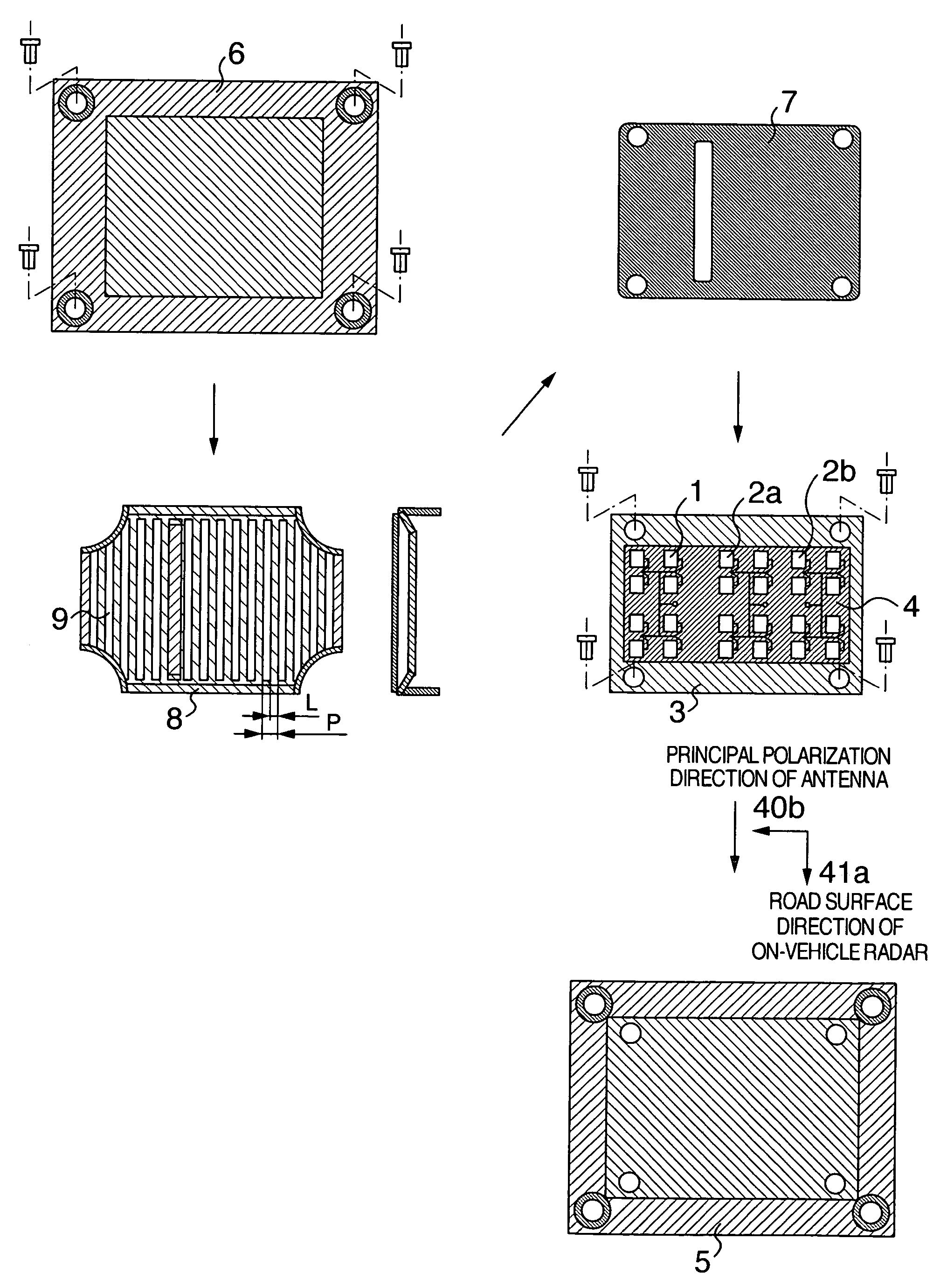
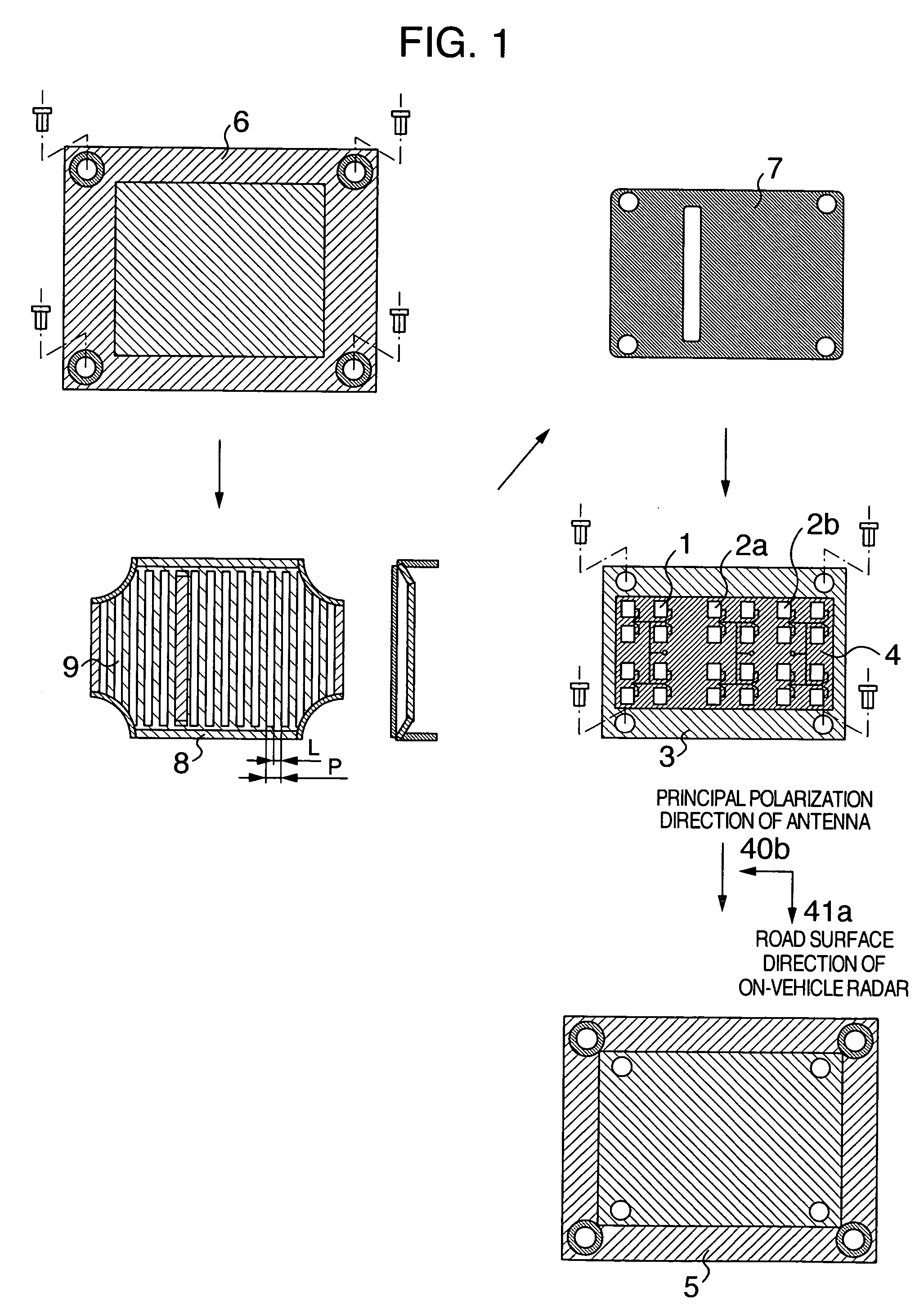
[0047]FIG. 1 is a configuration diagram showing a first embodiment of an on-vehicle radar according to the present invention. An arrow 41a indicates the direction of a road surface when the on-vehicle radar is attached to a vehicle.

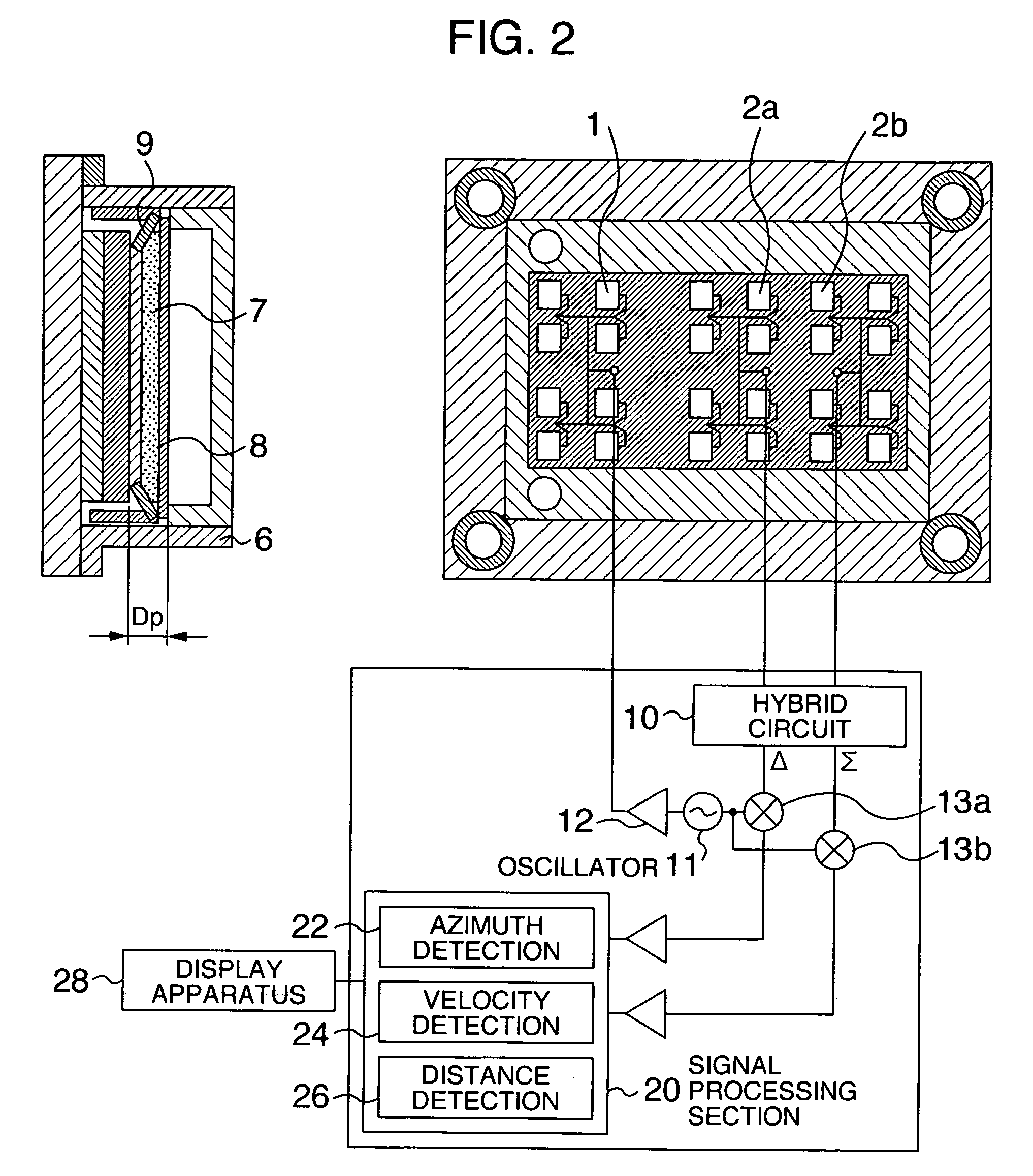
[0048] In this embodiment, a transmission signal is transmitted from a transmission patch antenna 1, a signal reflected by a target is received by a reception patch antenna 2a and a reception patch antenna 2b and the velocity, distance and azimuth of the target are detected from these reception signals. The transmission patch antenna 1 and reception patch antennas 2a, 2b formed on a dielectric substrate 4 are arranged on an antenna plate 3 made of metal, the antenna plate 3 is attached to a radar housing 5 and covered with a dielectric radome 6. A slit plate 8 provided on the antenna front face with a foamed sheet 7 interposed in between is made of metal which is sufficiently thin with respect to the wavelength and constructed of slits having a width L s...

embodiment 2

[0065]FIG. 4 is a configuration diagram showing a second embodiment of the on-vehicle radar according to the present invention. This embodiment consists of the slit plate 8 outserted with respect to the foamed sheet 7 instead of the slit plate 8 and foamed sheet 7 according to the first embodiment. In this case, too, pressurizing and fixing the slit plate 8 to the antenna surface using the radome 6 placed at a position facing the antenna surface makes it possible to reduce resonance of the slits 9, suppress noise and thereby obtain excellent detection performance.

embodiment 3

[0066]FIG. 5 shows a spacer 14 made of dielectric, metal or radio absorber, instead of the foamed sheet 7 of Embodiment 1, placed between the antenna and slit plate 8 except the planes of projection of the patches in the direction of the normal to the plane of the antenna patch.

[0067] In this case, since this structure reduces resonance of the slit 9, suppresses noise and constitutes all the antenna patch sections with air, it reduces power loss of the antenna and it is particularly excellent.

[0068] Furthermore, by setting this thickness to a ⅛ effective wavelength to ½ effective wavelength, it is possible to control the distance between the slit plate 8 and antenna and suppress noise and thereby obtain excellent detection performance.

[0069] Furthermore, by pressurizing and fixing the slit plate 8 to the antenna surface using the radome 6 placed at a position of the slit plate 8 facing the antenna surface, it is possible to reduce resonance of the slits 9, suppress noise and ther...


PUM


Abstract

A small, light and low-cost on-vehicle radar which reduces noise caused by a road surface, own car and radar itself, prevents road clutter and improves detection performance is provided. The on-vehicle radar includes an antenna having one or a plurality of radiation elements which radiate linearly polarized waves, a slit plate provided with a plurality of slits on a metal plate disposed in front of this antenna surface and a foamed material provided between the antenna and slit plate. Side lobes whose principal component is a cross polarized wave from a feeder line of the antenna can be reduced and road clutter can be prevented. Resonance of slits whose characteristic frequency becomes equal to or smaller than the frequency of vehicle can be reduced and noise can be suppressed. Therefore, it is possible to obtain excellent detection performance as the radar apparatus.

Description

BACKGROUND OF THE INVENTION [0001] The present invention relates to an on-vehicle radar, mounted on a moving body such as a vehicle for detecting an azimuth of an obstacle, relative distance from the moving body and relative velocity, etc. [0002] An on-vehicle radar using millimeter waves is hardly affected by meteorological conditions such as rain, fog, snow or dust and noise compared to an ultrasonic radar or laser radar, and therefore the on-vehicle radar is attracting attention as a radar ideally suited to collision prevention and follow-up driving of cars. [0003] In the above described application, as shown in FIG. 7, an on-vehicle millimeter-wave radar 20 is mounted on the front face of a moving body 21, a transmission signal is radiated to a target vehicle 22 from an antenna through a main lobe mb and it is possible to calculate a distance to the target vehicle 22 and velocity of the target vehicle, etc., by observing a frequency difference, phase difference, time difference,...

Claims


Application Information

Patent Timeline
IPC IPC(8): G01S13/90G01S13/931H01Q1/32H01Q1/42H01Q15/24H01Q19/02H01Q21/06
CPCG01S13/931G01S2013/9375H01Q1/3233H01Q1/425H01Q15/24G01S2013/9321H01Q19/028H01Q21/065G01S2013/9342G01S2013/9346H01Q19/021G01S2013/9318G01S2013/93185G01S2013/93271G01S7/2813G01S13/44
Inventor SASADA, YOSHIYUKIOUCHI, SHIROSHINODA, HIROSHI
Owner HITACHI LTD
Why Eureka
Try Eureka