Exhaust gas processing method and exhaust gas processing system

a processing method and exhaust gas technology, applied in the field of exhaust gas processing methods and systems, can solve the problems of ultra-fine particles with diameters of 2.5 m or smaller, which have recently become a problem on anti-pollution measures, and the need for filtering with extremely fine meshes, etc., to achieve easy and efficient collection of floating particulate matter, easy condense even a small amount, and low electric resistance

Inactive Publication Date: 2007-01-04
NISSIN ELECTRIC CO LTD +2
View PDF6 Cites 25 Cited by
  • Summary
  • Abstract
  • Description
  • Claims
  • Application Information

AI Technical Summary

Benefits of technology

[0030] By applying a high voltage to a high-voltage electrode and generating corona discharge in exhaust gas, it is possible to electrify the floating particulate matter in the exhaust gas and result in the cohesion and non-uniform distribution of the matter on a low-voltage electrode or near the electrode. Moreover, the exhaust gas is divided into high-concentration exhaust gas in which the concentration of the floating particulate matter is high and low-concentration exhaust gas in which the concentration of the matter is low. Therefore, it is possible to easily condense even a particulate matter with a comparatively low electric resistance that re-entrains in the case of electric dust collection, like the PM in the exhaust gas emitted by diesel engines.
[0031] Moreover, in the case of high-concentration exhaust gas, it is possible to easily and efficiently collect the floating particulate matter even by a wide-mesh filter, and only a small pressure-loss occurs, because the cohesion ...

Problems solved by technology

On the other hand, in the case of the PM which causes air contamination, ultra-fine particles with diameters of 2.5 μm or smaller (particularly, with diameters of tens of nanometers) referred to as PM2.5 have recently become a problem on antipollution measures.
However, when collecting the ultra-fine particles using only a DPF method, a filter with extremely fine meshes is necessary.
Therefore, it is very difficult to collect the ultra-fine particles without a large pressure loss.
However, though the electric dust collector captures electrified particulate matter by using electrostatic force and using a vessel wall surface with a low voltage potential (generally, ground potential) as a dust-collecting electrode, there is a problem that a purifying performance is deteriorated in a comparatively short time (for example, in several...

Method used


Image

  • Exhaust gas processing method and exhaust gas processing system
  • Exhaust gas processing method and exhaust gas processing system
  • Exhaust gas processing method and exhaust gas processing system

Examples


embodiment 1

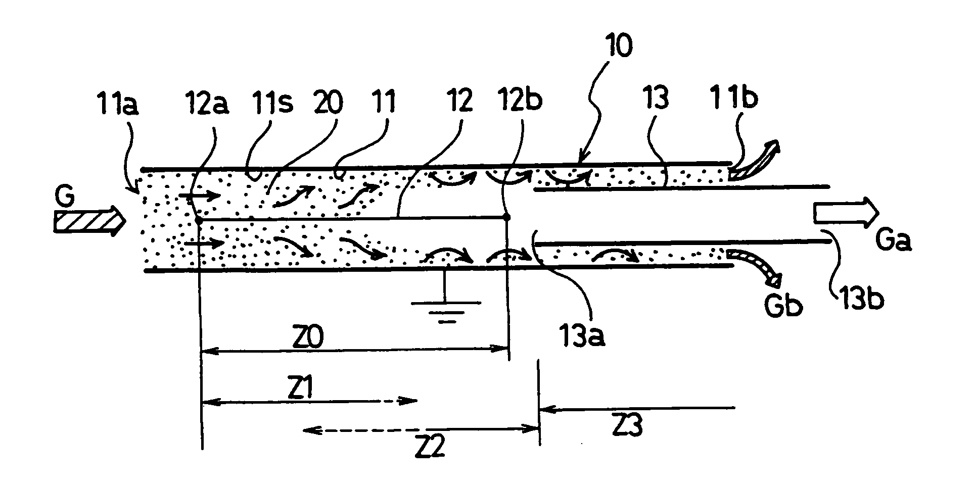
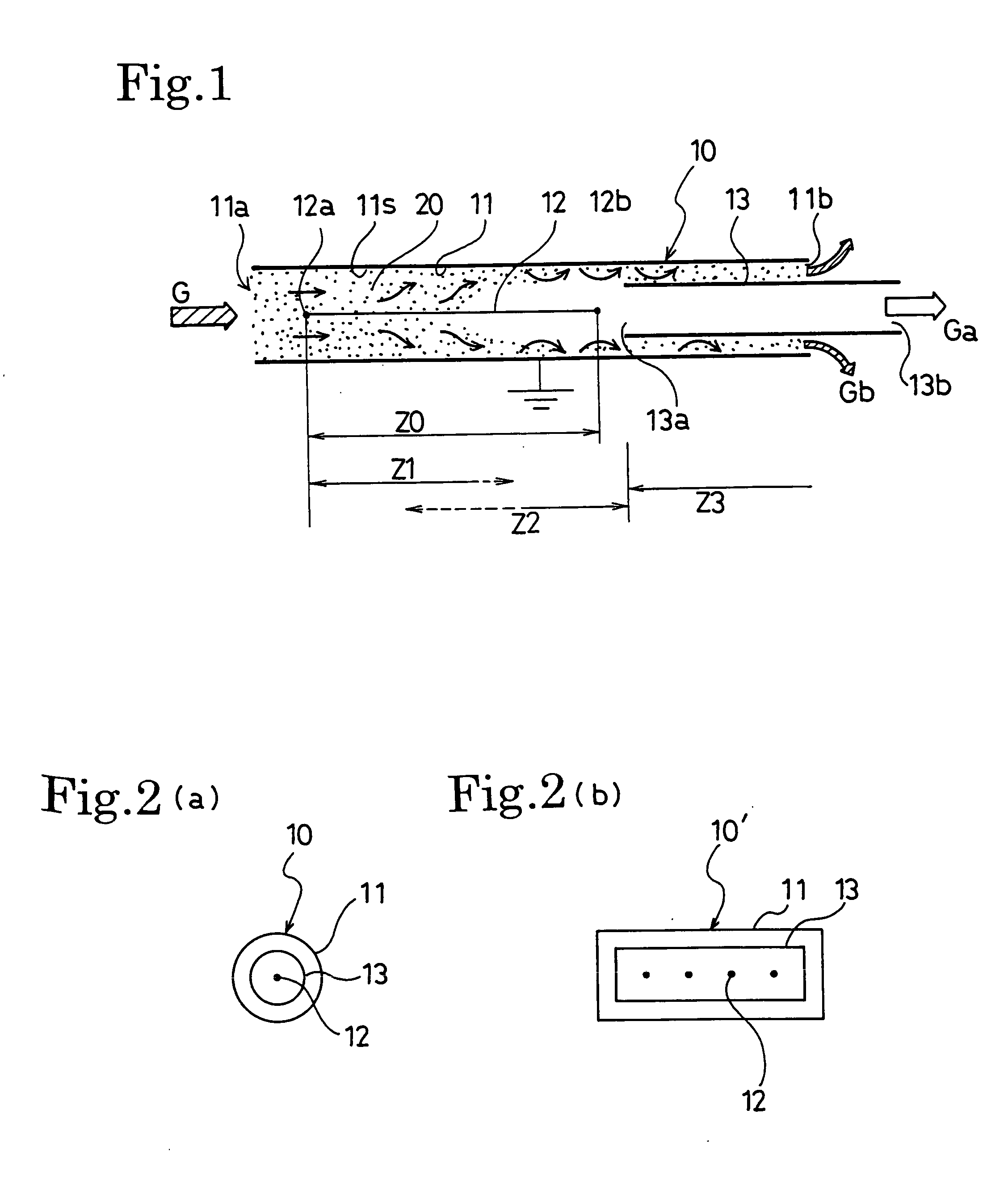
[0095] In the case of the exhaust gas processing system 10 of the first embodiment shown in FIGS. 1 and 2 (a), the high-voltage electrode 12 is formed of a stainless wire with a diameter of 0.2 mm φ, the low-voltage electrode 11 is formed by a stainless cylinder with an inside diameter of 38 mm φ, and the inner cylinder 13 is formed of a stainless cylinder with an inside diameter of 15 mm φ. The ratio between the inside and outside cross-sectional area of a cylinder becomes 5:3.

[0096] The exhaust gas processing system 10 is directly connected to the exhaust gas pipe area of a small diesel power generator (maximum output of 5 kW) to perform an experiment under an operation condition at 2.4 kW (48%) load. A voltage of −10 kV and a current of 0.4 mA are supplied to a high-voltage electrode by using a negative electrode direct high voltage power supply. The temperature of the exhaust gas processing system 10 is set to 100-200° C., flow rate of exhaust gas is set to approx. 200 L / min (i...

embodiment 2

[0100] In the case of the exhaust gas processing system 10C of the fourth embodiment shown in FIGS. 6 and 7 (a), the high-voltage electrode 12 is formed of a stainless wire with a diameter of 0.6 mm φ, the low-voltage electrode 11 is formed of a stainless cylinder with an inside diameter of 58 mm φ, and the outer cylinder 14 is formed of a stainless cylinder with an outside diameter of 220 mm φ. The filter 16 is provided to three layers by punching metal with a pore diameter of 1 mm at 2-mm pitch.

[0101] The exhaust gas processing system 10C is directly connected to the exhaust gas pipe area of a 2-ton truck to perform an experiment under conditions of an engine speed of 550 rpm, exhaust gas temperature of approx. 70° C., and exhaust gas quantity of approx. 1,400 L / min. A voltage of −18 kV is applied to a high-voltage electrode by using a negative electrode direct high voltage power supply. The retention time at the electrifying area (length of 300 mm) is approx. 30 ms and the reten...

embodiment 3

[0104] In the case of the exhaust gas processing system 10D of the fifth embodiment shown in FIG. 8, an experiment is performed in the same dimension and condition as the case of the embodiment 2 to collect the PM in exhaust gas by using glass fiber filter paper having a 0.3 μm φ particle with capturing rate of 99.9% or more and aspirating the re-merging exhaust gas Gc by a constant-flow-rate pump.

[0105] As a result, a clear difference between the cases of presence of discharge and absence of discharge is observed in the filter paper through which the exhaust gas Gc passes. Thereby, it is found that the PM is extremely decreased by applying a voltage to a corona discharge electrode.


PUM

PropertyMeasurementUnit
Concentrationaaaaaaaaaa

Abstract

An exhaust gas processing method and an exhaust gas processing system for controlling the spatial density distribution of particulate matter in exhaust gas by utilizing corona discharge in exhaust gas containing floating particulate matter such as diesel engine exhaust gas to form a relatively particulate matter-rich area and a relatively particulate matter-lean area, and diving exhaust gas particulates to the former and the latter. An exhaust gas processing system (10) provided with a high-voltage electrode (12) and a low-voltage electrode (11), wherein exhaust gas G is allowed to flow between the facing high-voltage electrode (12) and low-voltage electrode (11), and a high voltage is applied to between the counter electrodes to generate corona discharge in the exhaust gas G, whereby floating particulate matter (20) in the exhaust gas G is charged, the spatial density distribution of the floating particulate matter in the exhaust gas is controlled by an electrostatic force between the counter electrodes, and the exhaust gas G is divided into a high-concentration exhaust gas Gb in the vicinity of the low-voltage electrode where a particulate matter concentration is relatively high and a low-concentration exhaust gas Ga in the vicinity of the high-voltage electrode where a particulate matter concentration is relatively low.

Description

FIELD OF THE INVENTION [0001] The present invention relates to an exhaust gas processing method and system for collecting floating particulate matter in exhaust gas using corona discharge. DESCRIPTION OF RELATED ART [0002] To remove floating particulate matter (particulate matter: hereafter referred to as PM) included in the exhaust gas emitted by diesel engines, a technique that collects the particulate matter with a filter, referred to as a diesel particulate filter (hereafter referred to as DPF), so as to decrease the quantity of PM to be externally discharged is being developed. [0003] On the other hand, in the case of the PM which causes air contamination, ultra-fine particles with diameters of 2.5 μm or smaller (particularly, with diameters of tens of nanometers) referred to as PM2.5 have recently become a problem on antipollution measures. It is considered that ultra-fine particles are also discharged from the direct-injection gasoline engine that is frequently used as an aut...

Claims


Application Information

Patent Timeline
IPC IPC(8): F01N3/00F01N3/02B01D46/42B01D51/00B03C3/02B03C3/04B03C3/36B03C3/41B03C3/49F01N3/01
CPCF01N3/01F01N3/021Y02T10/20B03C3/06B03C3/155B03C3/41B03C2201/30B03C3/62B03C3/64B03C2201/04B03C2201/08B03C2201/12B03C3/49Y02T10/12B03C3/51
Inventor NAITO, KENTASENBAYASHI, SATORUKASAI, JUNICHIMIZUNO, AKIRA
Owner NISSIN ELECTRIC CO LTD
Why Eureka
Try Eureka