Optical wavelength converter and image forming apparatus using the same

Inactive Publication Date: 2007-01-04
CANON KK
View PDF3 Cites 17 Cited by
  • Summary
  • Abstract
  • Description
  • Claims
  • Application Information

AI Technical Summary

Benefits of technology

[0012] According to the present invention, by a relatively simple control method, it is possible to ensure thermal stability of the DBR laser and the optical waveform conversion device to realize an optical waveform converter or an optical wavelength conversion method which are capable of stably

Problems solved by technology

A blue-violet semiconductor laser has only recently been input into practical use but a semiconductor laser of a wavelength band of not more than green or ultraviolet region has not been commercialized as yet.
As a result, an output of the SHG light from the S

Method used


Image

  • Optical wavelength converter and image forming apparatus using the same
  • Optical wavelength converter and image forming apparatus using the same
  • Optical wavelength converter and image forming apparatus using the same

Examples


Example

Embodiment 1

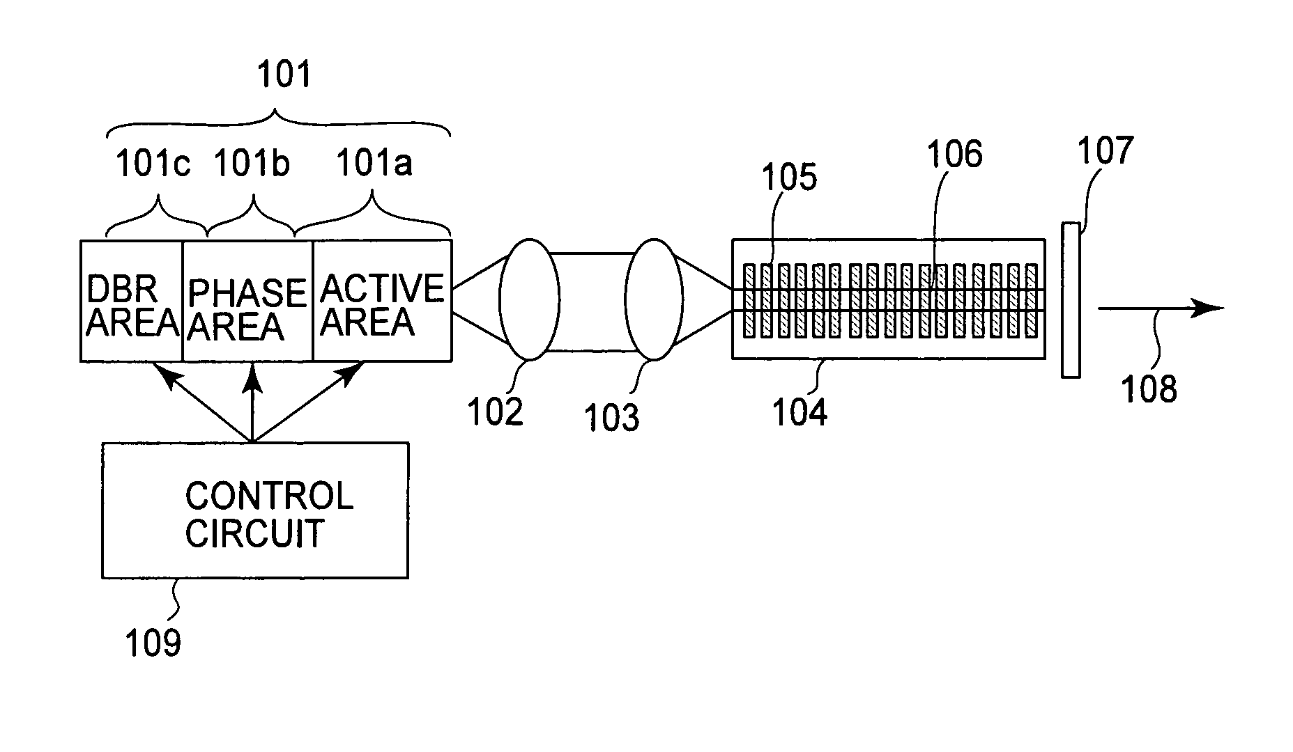
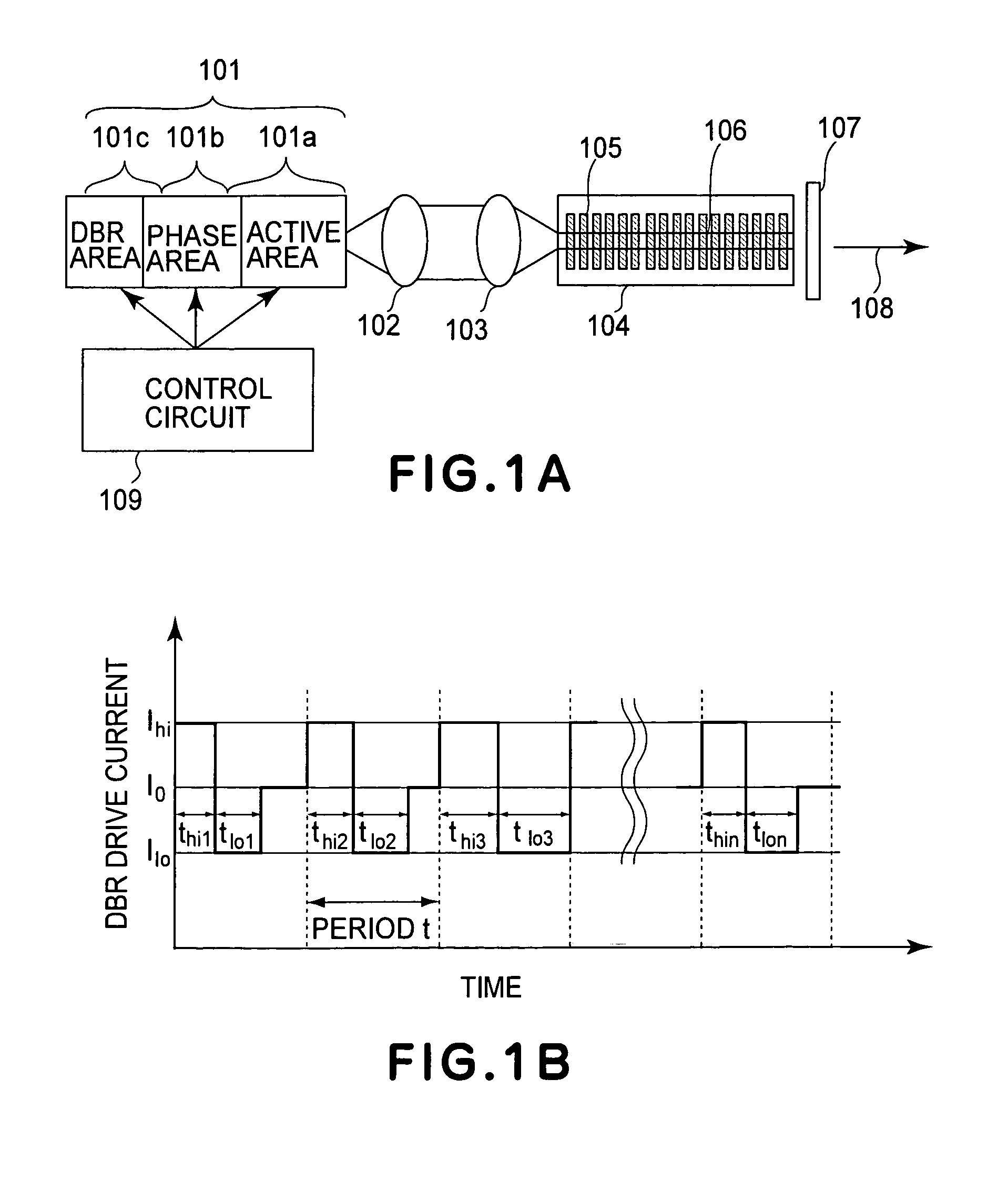
[0044]FIG. 1A shows a constitution of an optical waveform converter according to Embodiment 1 of the present invention. The optical waveform converter include a semiconductor DBR laser 101 has an active area 101a, a phase area 101b, and a DBR area 101c provided with a diffraction grating structure. In the phase area 101b and the DBR area 101c, an emission wavelength can be changed by passing a current through pn junction in a perpendicular direction to change a refractive index of an active layer.

[0045] A current is passed through the active area 101a, the phase area 101b, and the DBR area 101c by a control circuit 109 to concentrate fundamental wave laser light generated by the semiconductor DBR laser 101 at an SHG device through a collimator lens 102 and a condensing lens 103. The SHG device 104 is a waveguide-type quasi-phase adjustment device formed in a device length of 12 mm of LiNbO3 and provided with an optical waveguide 106 including periodically formed polari...

Example

Embodiment 2

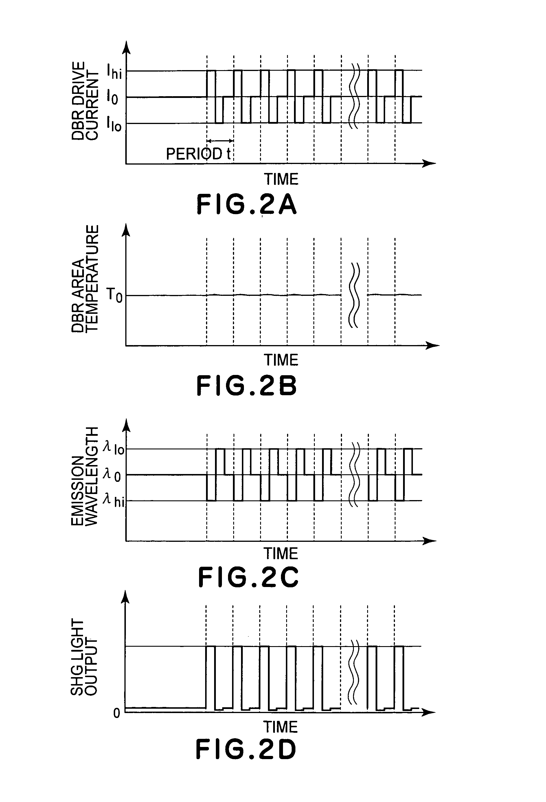
[0051] In Embodiment 1, the wavelength λhi, during the injection of the current Ihi into the DBR area 101c of the semiconductor DBR laser 101 is adjusted to the phase adjustment wavelength of the SHG device 104. In this embodiment, the wavelength λ0 during the injection of the current I0 into the DBR area 101c is adjusted to the phase adjustment wavelength of the SHG device 104. In addition, in modulation of drive current in the DBR area in this embodiment, a time width (duration) for injecting the current Ihi is extended and changed from a start point of each period t as one reference time and a time width for injecting the current Ilo is extended and changed from a middle point of each period t as another reference time.

[0052] The constitution of the optical waveform converter in this embodiment is identical to that at the optical waveform converter shown in FIG. 1 in Embodiment 1 except that the temperature of the SHG device or the period (pitch) of the polarization...

Example

Embodiment 3

[0054] In Embodiments 1 and 2, the constant current is injected into the active area 101a. In this embodiment, a modulated current is injected into the active area 101a. The injection current injected into the DBR area 101c in this embodiment is similar to that shown in FIG. 7A in Embodiment 2 and is shown also in FIG. 8A. The injection current injected into the active area 101a is shown in FIG. 8B. In this embodiment, the modulated current (injection current) including two values of IG and Ith such that the pulse width does not depend on period is injected into the active area 101a. Ith is set to a threshold current or a value of not more than the threshold current. Points of Ith are set so that the modulated current to be injected into the DBR area 101c can be changed from Ihi to Ilo (or Ilo to Ihi) Examples of these points include those of the reference times in each period described in Embodiment 2. The pulse width for Ith may desirably be a width (duration) capable...


PUM


Abstract

An optical wavelength converter includes a distributed Bragg reflector laser having an active area, a phase area, and a distributed Bragg reflector area in which a distributed Bragg reflector is formed; an optical wavelength conversion device for receiving fundamental wave light emitted from said distributed Bragg reflector laser and outputting second harmonic wave light of the fundamental wave light; and a control circuit for controlling an emission wavelength and a light output by controlling an injection current to be injected into the distributed Bragg reflector laser for each period. The control circuit controls the injection current to be injected into the distributed Bragg reflector laser while satisfying a condition for controlling a light output mode of the distributed Bragg reflector laser so that light energy to be inputted into the optical wavelength conversion device in each period is constant and satisfying a condition for injecting a current into each of an active area, a phase area, and a distributed Bragg reflector area in each of periods in a mode of constant amount of generated heat so that an injection current-emission wavelength characteristic in the distributed Bragg reflector area is constant.

Description


Claims


Application Information

Patent Timeline
IPC IPC(8): H01S3/10
CPCG02F1/3532G02F1/3775G02F2202/20H01S5/005H04N9/3129H01S5/06253H01S5/06256H01S5/0683H01S5/0092
Inventor FURUKAWA, YUKIOYUASA, TAKASHI
Owner CANON KK
Why Eureka
Try Eureka