A kind of scr nano membrane denitration catalyst and its preparation method and application

A denitration catalyst and nano-membrane technology, applied in chemical instruments and methods, physical/chemical process catalysts, separation methods, etc., can solve the problems of difficult catalyst treatment, high catalyst manufacturing cost, and increased volume.

Inactive Publication Date: 2017-04-12
厦门宇净环保科技有限公司
View PDF2 Cites 0 Cited by
  • Summary
  • Abstract
  • Description
  • Claims
  • Application Information

AI Technical Summary

Problems solved by technology

[0003] The disadvantages of the honeycomb denitration catalyst are: 1) According to the fluid characteristics, the flow rate through the center point of the fluid channel is the fastest, and the closer to the channel wall, the slower the flow rate
The airflow generates direct current in the airflow channel passing through the catalyst, resulting in low utilization rate of active components on the surface of the catalyst and low catalytic efficiency; 2) In order to meet the requirements of the denitration index, the volume of the denitration device needs to be increased, which increases the cost input of the user; 3) Due to The catalyst raw material is integrally pressed and molded, which leads to high catalyst manufacturing cost; 4) the heavy metal consumption in the catalyst is large, which makes it difficult to dispose of the scrap catalyst

Method used

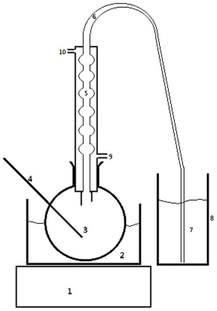
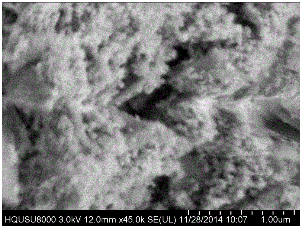
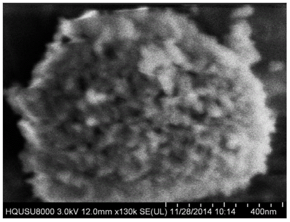

Image

  • A kind of scr nano membrane denitration catalyst and its preparation method and application
  • A kind of scr nano membrane denitration catalyst and its preparation method and application
  • A kind of scr nano membrane denitration catalyst and its preparation method and application

Examples


Embodiment 1

[0068] Embodiment 1: prepare nano-membrane catalyst I, compare the denitrification effect of catalyst I and traditional honeycomb catalyst:

[0069] A preparation method of SCR denitrification nano-membrane catalyst, using ceramic Pall ring (φ15×15) as carrier, with 25nm TiO 2 Nanoparticles are auxiliary carriers, based on the mass of the catalyst carrier, V 2 o 5 The loading mass fraction is 3.7%, MnO 2 The loading mass fraction of PdO is 2.8%, the loading mass fraction of PdO is 2.2%, WO 3 The loading mass fraction is 4.1%, CeO 2 The loading mass fraction is 0.3%, TiO 2 The loading mass fraction of nanoparticles is 86.9%; including the following steps:

[0070](1), carrier cleaning, drying: the carrier is washed 3 times with tap water to remove dust; then after cleaning 1 time with 40% hydrofluoric acid with a mass fraction, neutralize the residual acid on the carrier surface with 3% sodium hydroxide, and use Wash 3 times with tap water to remove residual alkali; wash ...

Embodiment 2

[0080] Embodiment 2: preparation catalyst II

[0081] A preparation method of SCR denitrification nano-membrane catalyst, using ceramic Pall ring (φ15×15) as carrier, with 25nm TiO 2 Nanoparticles and 100nm Fe 3 o 4 Nanoparticles are auxiliary carriers, based on the mass of the catalyst carrier, V 2 o 5 The loading mass fraction of PdO is 8%, the loading mass fraction of PdO is 2.5%, CeO 2 The loading mass fraction is 0.85%, WO 3 The loading mass fraction is 1.2%, TiO 2 The loading mass fraction of nanoparticles is 75%, Fe 3 o 4 The loading mass fraction of nanoparticles is 22.45%; including the following steps:

[0082] (1), carrier cleaning and drying: the carrier is washed with tap water to remove dust; then it is washed once with oleum, and the residual acid on the surface of the carrier is neutralized with 1% sodium hydroxide solution; it is washed 3 times with tap water, Remove residual lye; wash with distilled water for 3 times, then wash with deionized water f...

Embodiment 3

[0089] Embodiment 3: preparation catalyst III

[0090] A preparation method of SCR denitrification nano-membrane catalyst, using ceramic Pall ring (φ15×15) as carrier, with 25nm TiO 2 Nanoparticles are auxiliary carriers, based on the mass of the catalyst carrier, V 2 o 5 The loading mass fraction is 5%, MnO 2 The loading mass fraction is 2.8%, CeO 2 The loading mass fraction is 0.25%, WO 3 The loading mass fraction is 2.2%, TiO 2 The loading mass fraction of nanoparticles is 89.75%; including the following steps:

[0091] (1), carrier cleaning, drying: the carrier is washed with tap water to remove dust; then it is washed once with 40% hydrofluoric acid with a mass fraction; neutralize the residual hydrofluoric acid with 1% sodium hydroxide solution; Wash 3 times with tap water to remove residual lye on the surface; wash 3 times with distilled water, then wash 3 times with deionized water; vacuum dry at 150°C and 10Pa for 5 hours;

[0092] (2) Carrier surface modificat...


PUM

PropertyMeasurementUnit
denitrification rateaaaaaaaaaa

Abstract

The invention discloses a SCR nanofilm denitration catalyst, and a preparation method and applications thereof. According to the preparation method, industrial-grade common ceramic with changeable flow morphology is taken as a nanofilm catalyst carrier; a nanoparticle is taken as an auxiliary carrier; a mixture obtained via combination of V2O5 with at least one ingredient selected from PdO, MnO2, and NiO is taken as an active component; CeO2 is taken as a catalytic active ingredient; WO3 is taken as an accessory ingredient; the carrier is subjected to cleaning and drying, and then is delivered into a reflux unit filled with ethidene diamine for surface modification; the auxiliary carrier is prepared into a solution, the modified carrier is added into the solution for pulling film forming; the film-formed carrier obtain via the former step is delivered into a vacuum drying oven so as to realize chemical bond connection of the carrier with the nanoparticle; an obtained product is delivered into a mixed solution of CeO2 and WO3 for pulling film forming; and at last the SCR nanofilm denitration catalyst is obtained via drying. The SCR nanofilm denitration catalyst can be used for removing nitrogen oxides generated in combustors; turbulent flow, rotational flow, and cross flow are caused when air flow is delivered through the SCR nanofilm denitration catalyst; catalyst surface utilization rate is increased by changing flow morphology of the air flow, and catalytic efficiency is increased.

Description

technical field [0001] The invention relates to a denitration catalyst, in particular to an SCR nano-membrane denitration catalyst and its preparation method and application, and belongs to the technical field of purification of gaseous pollutants. Background technique [0002] At present, the main methods for removing nitrogen oxides from burner tail gas are selective non-catalytic reduction (SNCR) and selective catalytic reduction (SCR). The SCR method is widely used due to its high denitrification efficiency and good stability. The SCR method belongs to the category of gas-solid surface chemical reactions, and various catalysts are used, but the honeycomb SCR denitrification catalyst is the most commonly used, accounting for about 75% of the denitrification catalyst usage. [0003] The disadvantages of the honeycomb denitration catalyst are: 1) According to the fluid characteristics, the flow velocity through the center point of the fluid channel is the fastest, and the ...

Claims


Application Information

Patent Timeline
Patent Type & Authority Patents(China)
IPC IPC(8): B01J23/656B01J23/89B01J23/34B01D53/86B01D53/94B01D53/56
CPCY02C20/30
Inventor 王睿杨城君郑贵泉林晓辉杜世睿
Owner 厦门宇净环保科技有限公司
Why Eureka
Try Eureka