

Liquid crystal display device
- Summary
- Abstract
- Description
- Claims
- Application Information
AI Technical Summary
Benefits of technology
Problems solved by technology
Method used
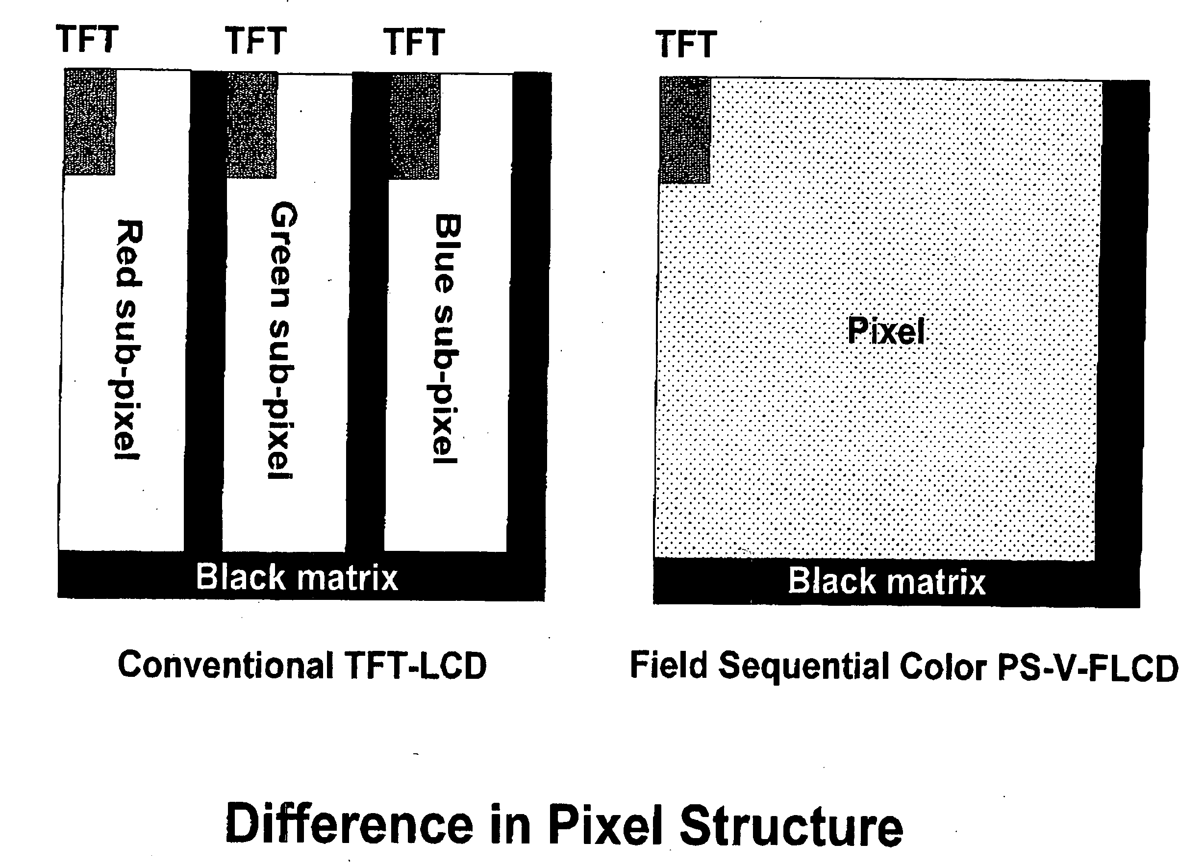
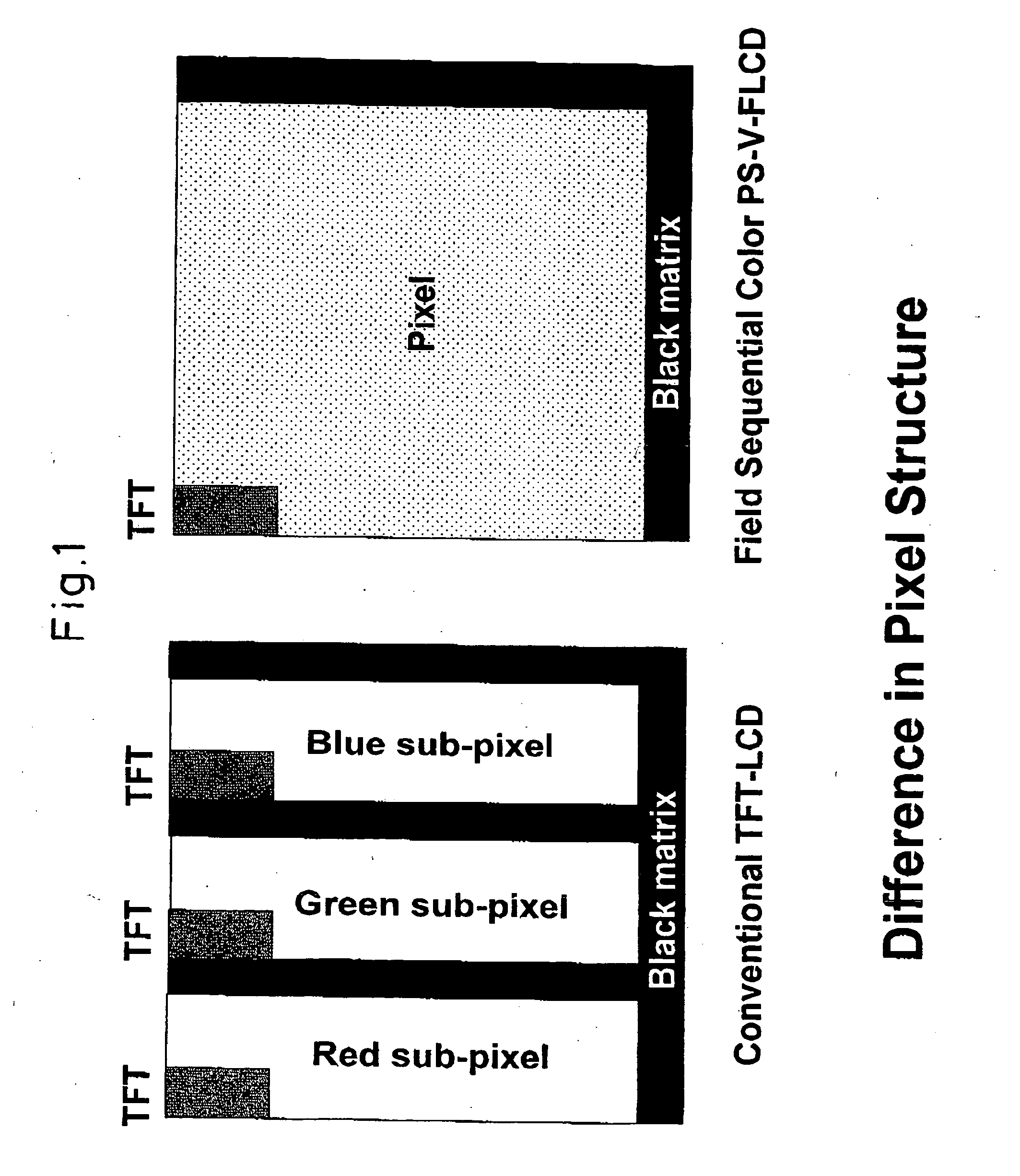
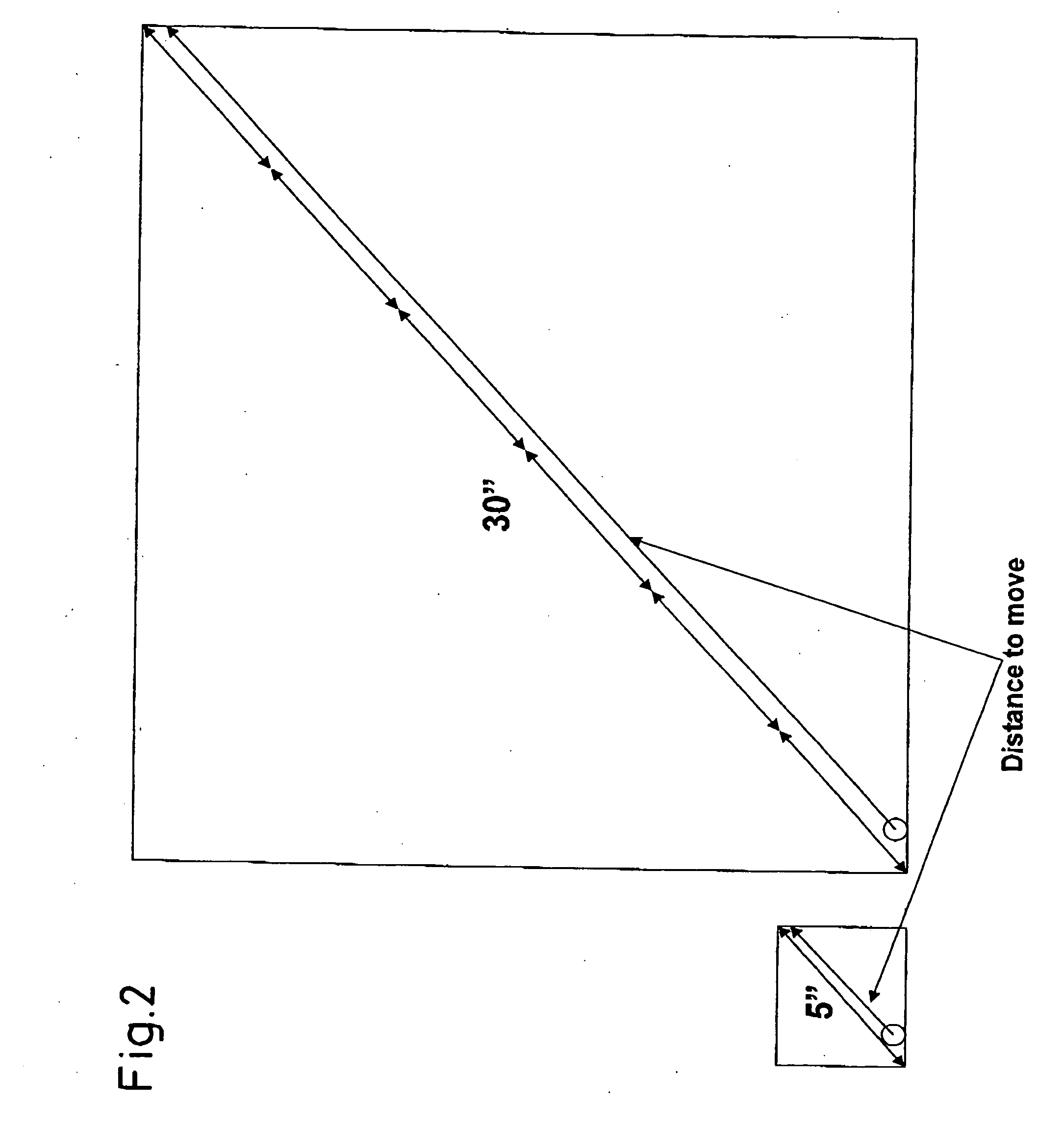
Image

Examples
example 1
[0210] (Present Invention)
[0211] Home made Smectic C phase liquid crystal mixture material was prepared. The major molecular structures of the mixture are followings:
[0212] The prepared non-spontaneous polarization Smectic liquid crystal mixture was doped with 3 wt % of the following molecular structure material. This total mixture is filled with the sample panel prepared as described bellow.
[0213] This particular doped material was prepared by following synthetic scheme.
[0214] After the mixing, the phase sequence of the mixture was measured as bulk material by using “hot stage” (type: HCS 206) manufactured by Instec: Colorado corporation, and the polarized microscope manufactured by Nikon: Japanese corporation. The mixture shows Smectic C phase at the room temperature as a bulk shape. The Smectic C phase shows molecular director tilt from the Smectic layer normal, so that the extinction angle under the closed Nicole has some tilt from the layer normal.
[0215] Isotropic to Ne...
example 2
[0220] (Control)
[0221] Using commercially available two-bottle system FLC mixture material
[0222] (Merck: ZLI-4851-000 and ZLI-4851-100), and opposite chirality material with those FLC mixture, almost zero-spontaneous polarization mixture was prepared. The prepared mixture contains 75 wt % of ZLI-4851-000, 20 wt % of ZLI-4851-100, and 5 wt % of opposite chirality material. For liquid crystal molecular alignment material, RN-1199 (Nissan Chemicals Industries) was used as 1 to 1.5 degrees of pre-tilt angle alignment material. Thickness of the alignment layer as cured layer was set at 1,000 A to 1,200 A. The surface of this cured alignment layer was buffed by Rayon cloth in the direction of 30 degrees to, center line of the substrate. The contact length of the buffing was set to 0.4 mm at both substrates. Silicon dioxide balls with average diameter of 1.6 μm are used as spacers. Obtained panel gap as measured was 1.8 μm. The above mixed material was injected into the panel at the isot...
example 3
[0224] (Control)
[0225] Home made Smectic C phase liquid crystal mixture material was prepared. The major molecular structures of the mixture are followings:
[0226] The phase sequence of the mixture was measured as bulk material by using “hot stage” (type: HCS 206) manufactured by Instec: Colorado corporation, and the polarized microscope manufactured by Nikon: Japanese corporation. The mixture shows Smectic C phase at the room temperature as a bulk shape. The Smectic C phase shows molecular director tilt from the Smectic layer normal, so that the extinction angle under the closed Nicole has some tilt from the layer normal.
[0227] Isotropic to Nematic: 92 deg.C., Nematic to Smectic A: 83 deg.C., Smectic A to Smectic C: 79 deg.C., Smectic C to Crystal: 13 deg.C. This mixture was filled with the sample panel prepared as following.
[0228] For liquid crystal molecular alignment material, RN-1199 (Nissan Chemicals Industries) was used as less than 1.5 degrees of molecular pre-tilt angle...
PUM
 Abstract
Description
Claims
Application Information