Free radical initiator in remote plasma chamber clean

a technology of initiator and free radical, applied in the direction of liquid cleaning, coating, chemistry apparatus and processes, etc., can solve the problems of deposition process performance drift, loss of production yield, and accumulation of unwanted films and particulates on surfaces other than the target substrate, so as to enhance the remote plasma cleaning of semiconductor deposition process chambers, reduce the cleaning time, and reduce the temperature chambers

Inactive Publication Date: 2007-01-11
AIR PROD & CHEM INC
View PDF14 Cites 28 Cited by
  • Summary
  • Abstract
  • Description
  • Claims
  • Application Information

AI Technical Summary

Benefits of technology

[0015] an ability to reduce the cleaning time through optimization of a reduced temperature chamber clean;
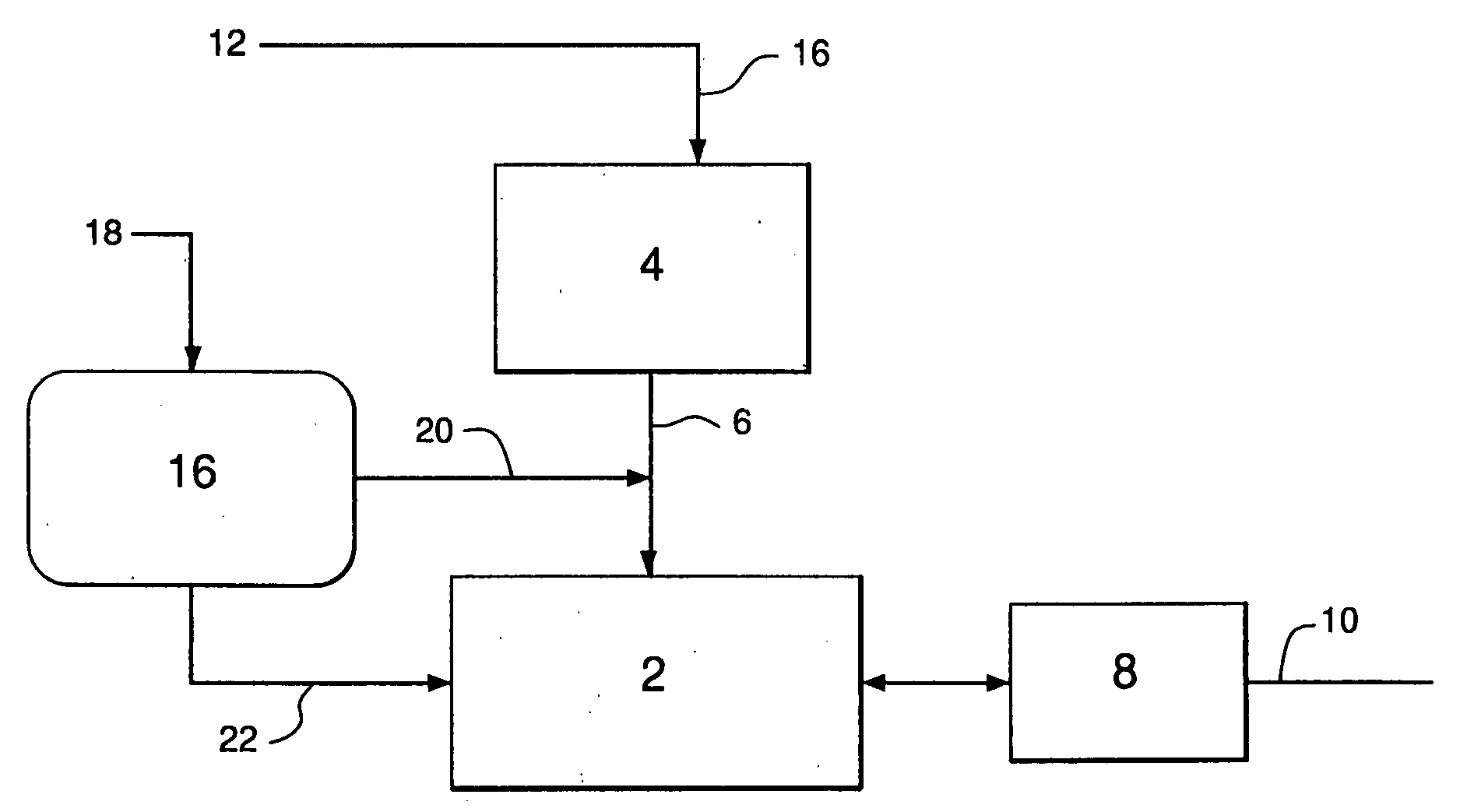
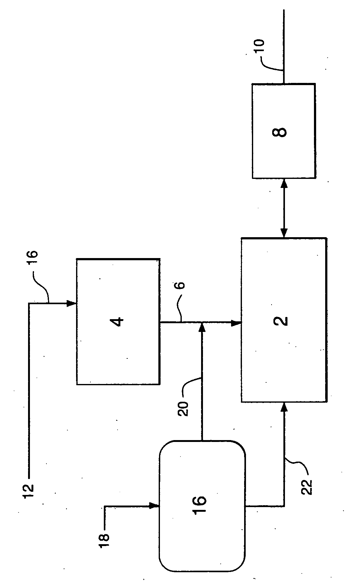
[0016] an ability to enhance the remote plasma cleaning of semiconductor deposition process chambers by using free radical initiators to suppress the recombination of free radicals formed in the plasma generator prior to reaction with the unwanted residue;
[0017] an ability to minimize free radical recombination, e.g., fluorine atom recombination, prior to reaction with unwanted residue in the deposition process chamber and thereby increase the efficiency of reactant utilization and efficiency of chamber cleaning; and,
[0018] an ability to reduce reactant emission from the effluent from the deposition process chamber, and thereby reduce the load and cost of reactant abatement and minimize toxic gas emissions.

Problems solved by technology

Generally, all methods of film deposition result in the accumulation of unwanted films and particulate materials on surfaces other than the target substrate, that is, the deposition materials also collect on the walls, tool surfaces, susceptors, and on other equipment employed in the deposition process.
These unwanted solid residues can change the reactor surface characteristics and RF power coupling efficiency as well as lead to deposition process performance drifts, and loss of production yield.
Moreover, accumulated solid residues also can flake off from the deposition reactor internal surface, and deposit onto a wafer surface causing device defects.
One of the problems of remote plasma cleaning resides in the fact that a large part of the free radicals formed in the plasma generator recombine into an inert form by the time they reach the process chamber.
Therefore, a substantial portion of the reactant gas is wasted resulting in low utilization efficiency.

Method used


Image

  • Free radical initiator in remote plasma chamber clean
  • Free radical initiator in remote plasma chamber clean

Examples


Embodiment Construction

[0020] In the manufacture of semiconductor integrated circuits (IC), opto-electronic devices, and microelectro-mechanical systems (MEMS), multiple steps of thin film deposition are performed in order to construct several complete circuits (chips) and devices on monolithic substrate wafers. Each wafer is often deposited with a variety of thin films: conductor films, such as tungsten; semiconductor films such as undoped and doped poly-crystalline silicon (poly-Si), doped and undoped (intrinsic) amorphous silicon (a—Si); dielectric films such as silicon dioxide (SiO2), undoped silicon glass (USG), boron doped silicon glass (BSG), phosphorus doped silicon glass (PSG), and borophosphorosilicate glass (BPSG), silicon nitride (Si3N4), silicon oxynitride (SiON) etc.; low-k dielectric films such as fluorine doped silicate glass (FSG), and carbon-doped silicon glass (CDSG), such as “Black Diamond”. Thin film deposition can be accomplished by placing the substrate (wafer) into an evacuated pro...


PUM

PropertyMeasurementUnit
temperaturesaaaaaaaaaa
temperatureaaaaaaaaaa

Abstract

This invention relates to an improvement in the remote plasma cleaning of CVD process chambers and equipment from unwanted deposition byproducts formed on the walls, surfaces, etc. of such deposition process chambers and equipment. The improvement in the remote cleaning process resides in providing a free radical initiator downstream of the remote plasma generator employed for producing said plasma, said free radical initiator capable of forming free radicals in the presence of said plasma.

Description

BACKGROUND OF THE INVENTION [0001] In the electronics industry, various film deposition techniques have been developed wherein selected materials are deposited on a target substrate to produce electronic components such as semiconductors. One type of film deposition process includes chemical vapor deposition (CVD) wherein gaseous reactants are introduced into a heated processing chamber, vaporized and films formed on the desired substrate. Other types of film deposition processes include plasma enhanced chemical vapor deposition (PECVD), and alternate vapor deposition (ALD). [0002] Generally, all methods of film deposition result in the accumulation of unwanted films and particulate materials on surfaces other than the target substrate, that is, the deposition materials also collect on the walls, tool surfaces, susceptors, and on other equipment employed in the deposition process. These unwanted solid residues can change the reactor surface characteristics and RF power coupling effi...

Claims


Application Information

Patent Timeline
Patent Type & Authority Applications(United States)
IPC IPC(8): B08B6/00B08B3/00
CPCC23C16/4405H01J37/32862H01J37/32357B08B7/00
Inventor JI, BING
Owner AIR PROD & CHEM INC
Why Eureka
Try Eureka