This helps you quickly interpret patents by identifying the three key elements:
Problems solved by technology
Method used
Benefits of technology
[0011] The present invention relates to a stereoscopic imaging system incorporating a plurality of imaging devices or cameras. The system generates a high resolution, wide field of view image database from which images can be combined to provide wide field of view or panoramic or omni-directional images. Wide field of view or panoramic images i
Problems solved by technology
First, the speed of image capture is limited by the rotational speed of the servo-mechanism and inertia of the assembly.
This can place significant performance limits on the frame-rate and shutter-rate of the system as well as the speed with which users can scan the surroundings.
Second, reliance on moving elements for operation inherently possesses greater maintenance requirements and suspect reliability.
Third, multiple users of such a system are constrained to view the same part of the scene simultaneously, since only one direction can be viewed at a time.
However, while this approach may be affordable and relatively prevalent, it also suffers from a number of significant drawbacks.
Because the entire scene is being captured by a single CCD (or similar image capture element), the total average information per pixel is significant, causing resolution loss.
More importantly, however, because this technique generally involves projecting a spherical surface onto a flat, rectangular image capture element (e.g. the CCD or CMOS chip), significant distortion is unavoidable, negatively impacting resolution.
Some amount of distortion can be processed out, but the information lost due
Method used
Image
Click on the blue label to locate the original text in one second.
Reading with bidirectional positioning of images and text.
Examples
Embodiment Construction
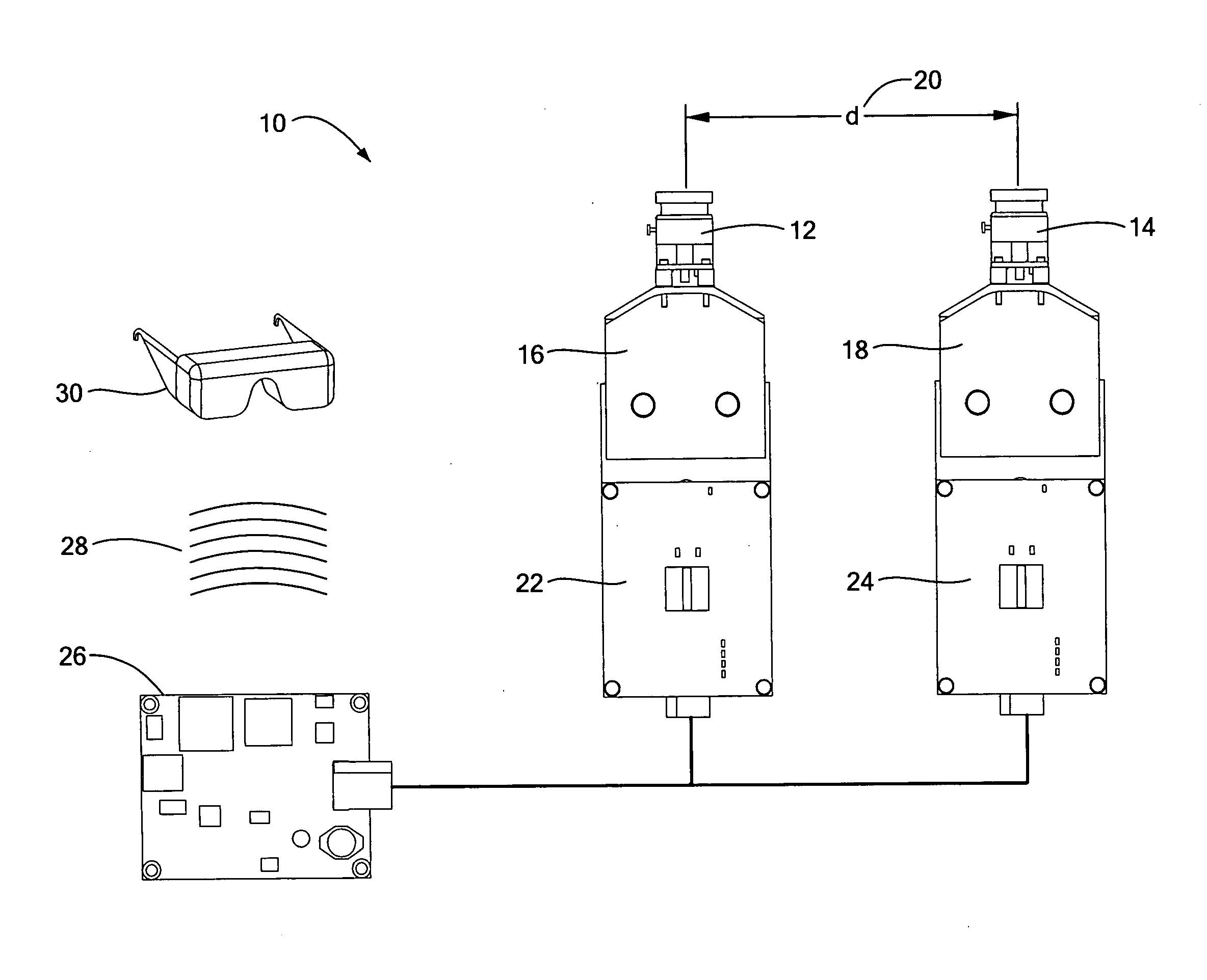
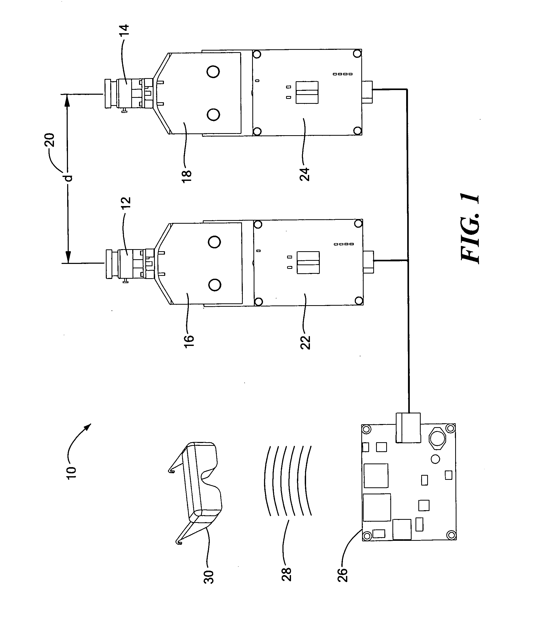
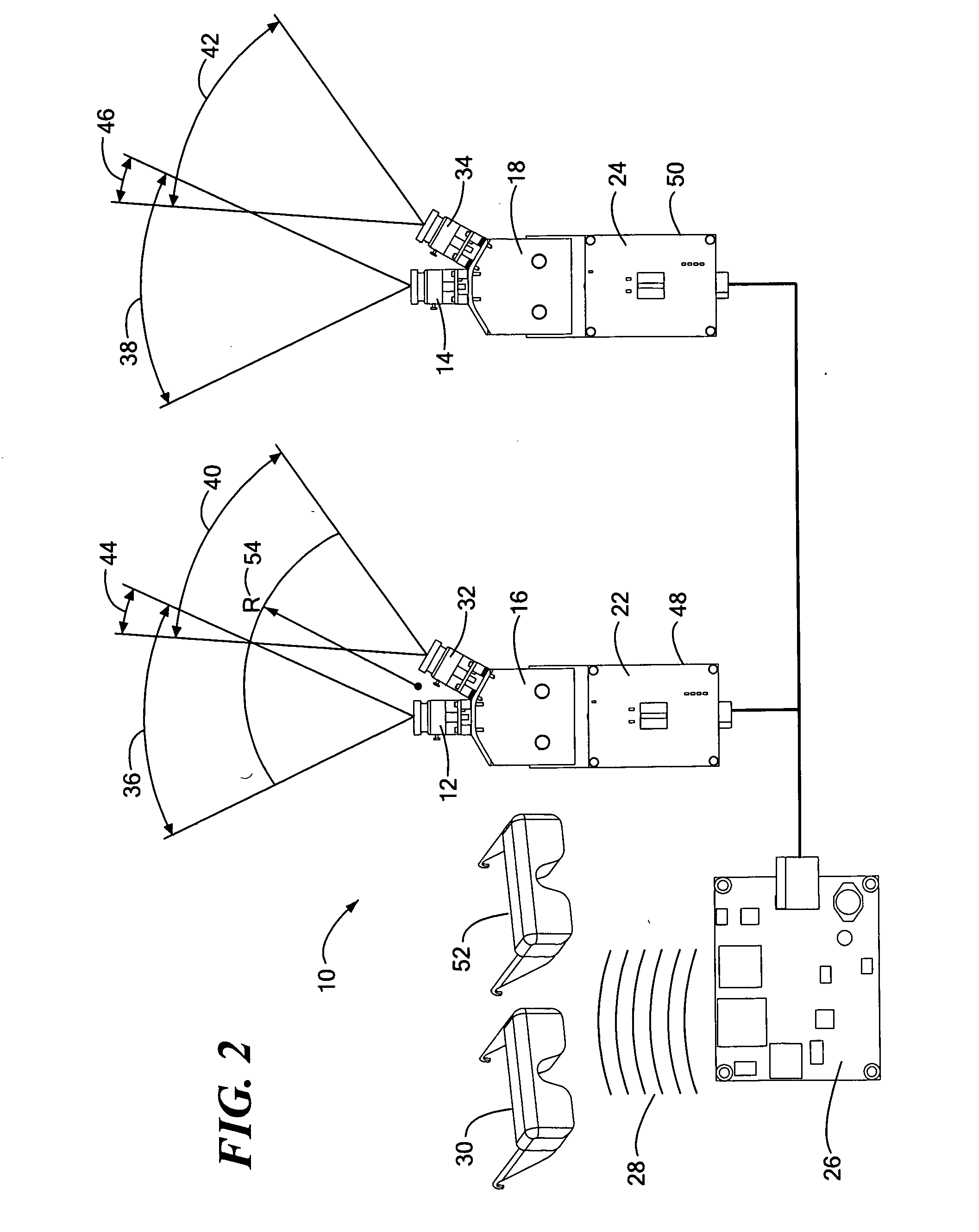
[0033] The present invention provides a stereoscopic imaging system having a plurality of imaging devices arranged to capture an image. The images from each imaging device are combined to provide a wide field of view (FOV) image or a panoramic or omni-directional image that can be transmitted to an end user device, such as a head mounted display (HMD), monitor, or projection device. An imaging device is typically considered to be one or more optical stages to focus a range of electromagnetic waves from a given field of view onto an imaging mechanism, which may be a charge-coupled device (CCD), a Complementary Metal Oxide Semiconductor (CMOS) optical sensor, traditional film, a microbolometer infrared array, or some other mechanism to capture and store optical information. An imaging device may also be referred to as a camera herein. The number of imaging devices is selected based on the application and is directly related to the pixel density of the optical sensor and the field of v...
PUM
Abstract
A stereoscopic imaging system incorporates a plurality of imaging devices or cameras to generate a high resolution, wide field of view image database from which images can be combined in real time to provide wide field of view or panoramic or omni-directional still or video images.
Description
CROSS REFERENCE TO RELATED APPLICATIONS [0001] This application claims the benefit under 35 U.S.C. §119(e) of U.S. Provisional Patent Application No. 60 / 594,429, filed Apr. 7, 2005, and U.S. Provisional Patent Application No. 60 / 594,430, filed Apr. 7, 2005, the disclosures of both of which are incorporated by reference herein.STATEMENT REGARDING FEDERALLY SPONSORED RESEARCH OR DEVELOPMENT [0002] This invention was made under NASA Contract Nos. NNJ04JC50C and NNJ05JE77C. The government has certain rights in this invention.BACKGROUND OF THE INVENTION [0003] The concept of stitching multiple camera images together in order to compose a wide field of view image is known, as is the concept of capturing multiple video signals to compose a panoramic or omni-directional image, with some stereographic functionality. See, for example, U.S. Pat. Nos. 5,703,604, 6,323,858, 6,356,397, 6,392,699, and 7,015,954 and U.S. patent application Ser. No. 2003 / 0117488. [0004] There are three general techn...
Claims
Application Information
Patent Timeline
Application Date:The date an application was filed.
Publication Date:The date a patent or application was officially published.
First Publication Date:The earliest publication date of a patent with the same application number.
Issue Date:Publication date of the patent grant document.
PCT Entry Date:The Entry date of PCT National Phase.
Estimated Expiry Date:The statutory expiry date of a patent right according to the Patent Law, and it is the longest term of protection that the patent right can achieve without the termination of the patent right due to other reasons(Term extension factor has been taken into account ).
Invalid Date:Actual expiry date is based on effective date or publication date of legal transaction data of invalid patent.