
Coating system for silicon based substrates

a coating system and silicon based technology, applied in the direction of superimposed coating process, natural mineral layered products, water-setting substance layered products, etc., can solve the problems of reducing flexural or tensile strength, accelerated oxidation and recession of materials at high temperature, and reducing substrate strength, etc., to reduce substrate strength, less flaws, and less damage

Active Publication Date: 2007-01-18
RAYTHEON TECH CORP
View PDF6 Cites 45 Cited by
  • Summary
  • Abstract
  • Description
  • Claims
  • Application Information

AI Technical Summary

Benefits of technology

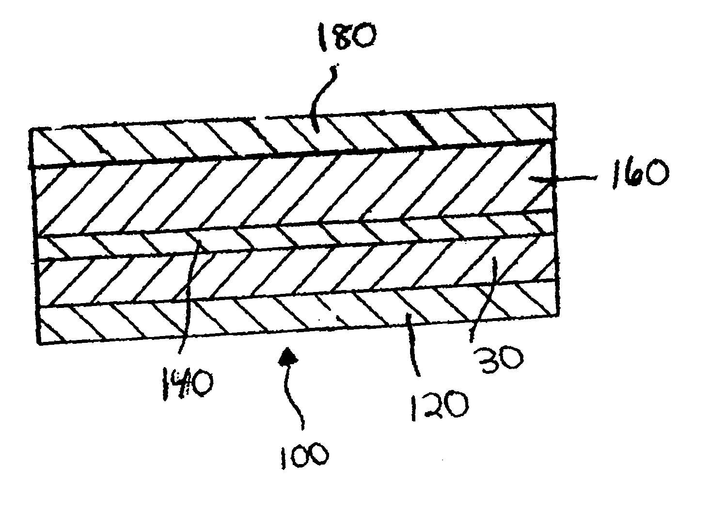
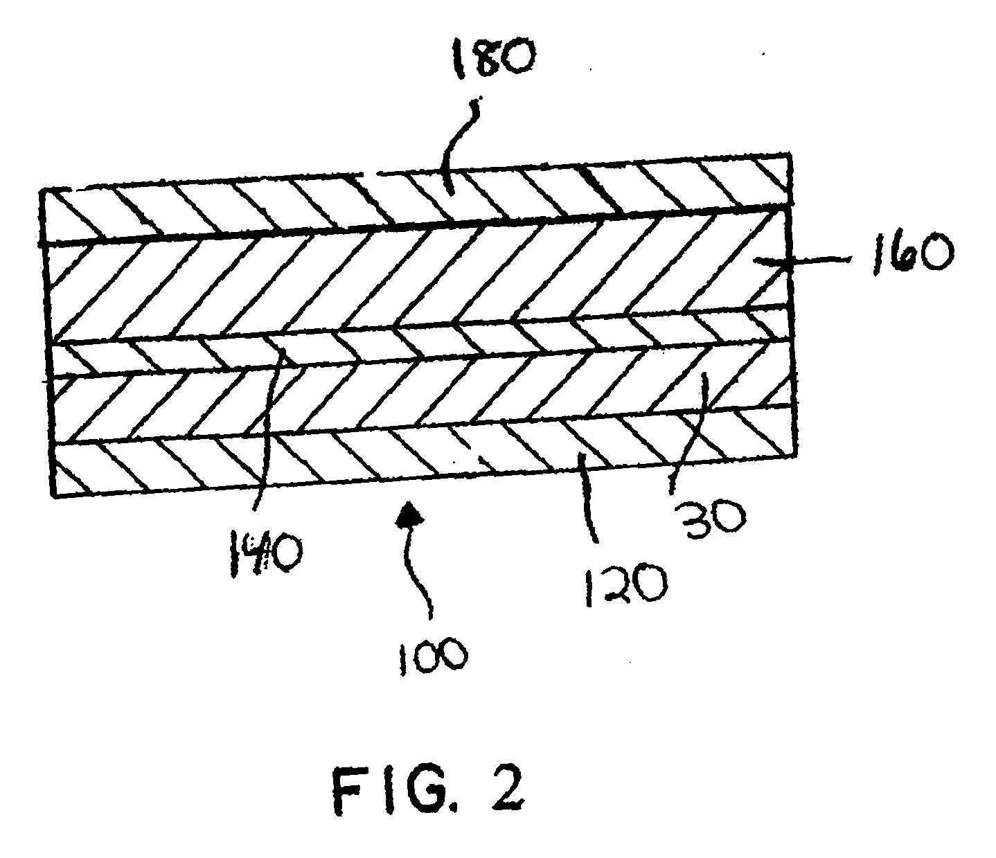
[0007] The foregoing object is achieved by the present invention wherein a compliant layer having an elastic modulus of between 30 and 130 GPa is provided between a silicon based substrate and an oxygen gettering layer. In the present invention, reduction in substrate strength is mitigated by making the coating system more flaw tolerant by supplying a compliant layer between the oxygen gettering layer and the substrate. The coating system thus retains the advantages of the prior art systems without debiting the strength of the substrate. The mitigation of the strength debit is brought about by the coating design of the present invention, which comprises a compliant layer, oxygen gettering layer, and additional barrier layer(s), which drives down the residual tensile stresses in the layers adjacent to the substrate and / or reduces the stored elastic strain energy of the coated system. Further, the compliant layer acts to buffer the stress concentration in the substrate thereby helping to retain the strength of the substrate. The bond coat system of the present invention is a significant improvement over prior art systems known to date.

Problems solved by technology

However, these materials exhibit accelerated oxidation and recession in high temperature, aqueous environments such as, for example, the combustor and turbine sections of gas turbine engines.
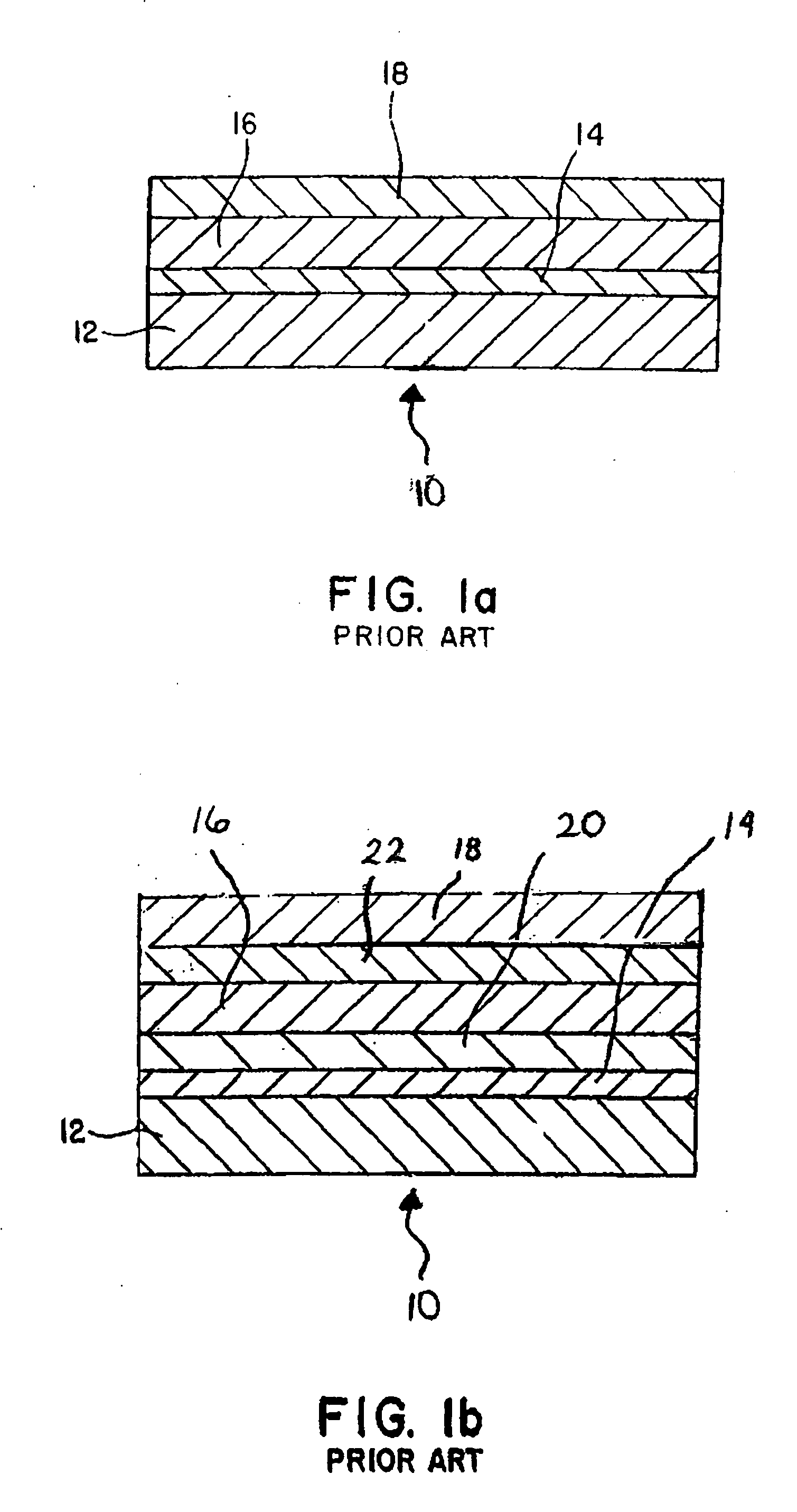
However, it has now been found that when the coatings depicted in the prior art are applied to some silicon-containing substrates such as silicon nitride, their mechanical properties suffer as demonstrated by a reduction in the flexure or tensile strength.
It is believed that a loss in mechanical properties results from mechanical incompatibilities between the bond coat 14 and silicon-containing substrate 12.
It is further found that failure in coating systems and brittle ceramics can occur due to high strains and stresses and / or high elastic stored energy in the system.
Due to the brittle nature of silicon bond coat and silicon-containing substrate, the thermal strains and the resulting thermal stresses can lead to cracking in the bond layer or substrate or cause delamination of the interface between the bond coat and substrate.
High thermal stresses may also lead to local stress concentrations and activate small defects or flaws in the bond coat or silicon-containing substrate leading to a failure well below the typical substrate strength.

Method used


Image

  • Coating system for silicon based substrates
  • Coating system for silicon based substrates
  • Coating system for silicon based substrates

Examples


example 1

[0018] 26.67 gm of yttrium disilicate (Y2Si2O7) was added to 10 ml of deionized water with 2.5% Darvan by weight (2.5 gm Darvan in 100 ml water). The slurry was ball milled for 30 minutes. Six silicon nitride bars were dipped in the slurry and dried. The coated bars were subsequently fired at 1350° C. for 5 hours. The dip process was repeated another time and the bars were refired at 1350° C. for 5 hours. Subsequently, the samples were introduced in a CVD reactor and coated with 35 and 70 microns of silicon. The reactor was maintained at 850-900° C. and the deposition of silicon was carried out as per the following reaction:

SiH2Cl2(g)+H2(g) Si(s)+2HCl(g)+H2 (g) [0019] The flexure strength of the coated samples was measured in four-point bending and the average strength was found to be comparable to that of the uncoated silicon nitride samples (FIG. 3). As can be seen from FIG. 3 the high strength of uncoated silicon nitride is maintained even after it is coated.

example 2

[0020] 31.33 gm of yttrium monosilicate (Y2SiO5) was added to 10 ml of water with 2.5% Darvan by weight (2.5 gm Darvan in 100 ml water). The slurry was ball milled for 30 minutes. Six silicon nitride bars were dipped in the slurry and dried. The coated bars were subsequently fired at 1350° C. for 5 hours. The dip process was repeated another time and the bars were refired at 1350° C. for 5 hours. Subsequently, the samples were introduced in a CVD reactor and coated with 20 microns of silicon. The reactor was maintained at 850-900° C. and the deposition of silicon was carried out as per the following reaction:

SiH2Cl2(g)+H2(g)→Si(s)+2HCl (g)+H2 (g) [0021] The flexure strength of the coated samples was measured in four-point bending and the average strength was found to be 90% of that of uncoated silicon nitride bars.

example 3

[0022] Air plasma spray was used to deposit 125 microns of silicon on a silicon nitride substrate. The flexure strength of coated bars was measured in four-point bending and the average strength was found to be approximately 50% of that of uncoated silicon nitride bars.


PUM

PropertyMeasurementUnit
Fractionaaaaaaaaaa
Thicknessaaaaaaaaaa
Thicknessaaaaaaaaaa

Abstract

A bond coat system for silicon based substrates wherein a compliant layer having an elastic modulus of between 30 and 130 GPa is provided between the silicon based substrate and a silicon metal containing oxygen gettering layer.

Description

U.S. GOVERNMENT RIGHTS [0001] The invention was made with U.S. Government support under contract N-00014-03-C-0477 awarded by the Department of the United States Navy. The U.S. Government may have certain rights in the invention.BACKGROUND OF THE INVENTION [0002] The present invention drawn to a bond coat system to be applied to a silicon containing substrate. [0003] Silicon-based monolithic ceramics such as, silicon carbide and silicon nitride, and composites such as, silicon carbide fiber reinforced silicon carbide matrix are attractive materials for use in gas turbine engine hot sections due to their high temperature mechanical and physical properties as well as lower density than metals. However, these materials exhibit accelerated oxidation and recession in high temperature, aqueous environments such as, for example, the combustor and turbine sections of gas turbine engines. In order to reduce the rate of oxidation and recession at high temperatures in substrates used as cerami...

Claims


Application Information

Patent Timeline
IPC IPC(8): B32B13/04B32B9/04B05D1/08C23C16/00C23C14/32B32B15/04B05D1/04B32B19/00
CPCC04B41/009C23C28/3455C04B41/89C04B41/52C23C28/345C23C28/341C23C28/34C23C28/321C23C28/322C04B41/4539C04B41/4582C04B41/5024C04B41/5044C04B41/522C04B41/5045C04B41/4531C04B41/5096C04B41/5027C04B35/565C04B35/584C04B35/806
Inventor BHATIA, TANIASCHMIDT, WAYDE R.TREDWAY, WILLIAM K.VEDULA, VENKATA R.
Owner RAYTHEON TECH CORP
Learn More