Magnetic memory cell, magnetic memory device, and magnetic memory device manufacturing method
a magnetic memory device and manufacturing method technology, applied in semiconductor devices, digital storage, instruments, etc., can solve the problems of insufficient to achieve improved storage speed and access speed, insufficient to realize magnetic memory devices of higher packing density, and difficulty in performing sufficiently stable writing, etc., to achieve processing with high alignment precision and simplify the whole manufacturing process
- Summary
- Abstract
- Description
- Claims
- Application Information
AI Technical Summary
Benefits of technology
Problems solved by technology
Method used
Image
Examples
first embodiment
[0085] First, by referring to FIGS. 1 to 7, the configuration of a magnetic memory device according to a first embodiment of the invention will be described.
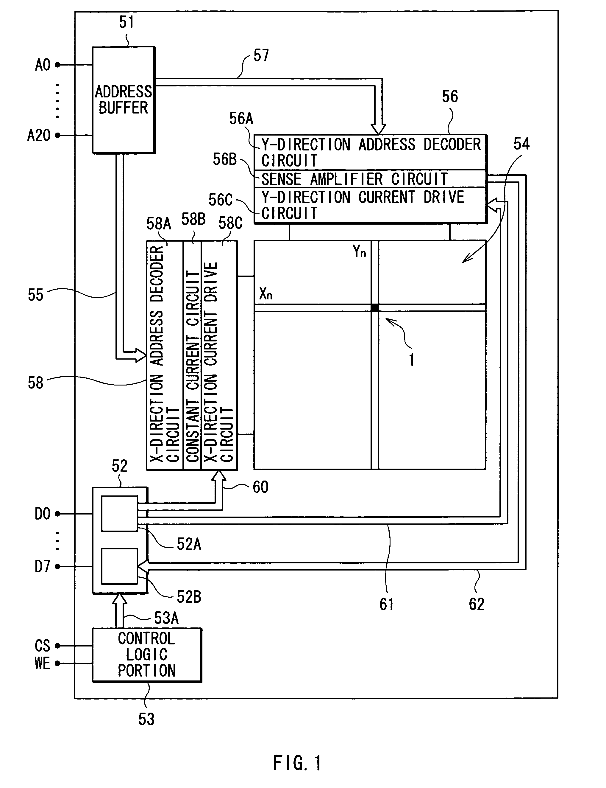
[0086]FIG. 1 is a conceptual diagram showing a general configuration of a magnetic memory device in the embodiment. The magnetic memory device has an address buffer 51, a data buffer 52, a control logic portion 53, a memory cell group 54, a first drive control circuit portion 56, a second drive control circuit portion 58, external address input terminals A0 to A20, and external data terminals D0 to D7.
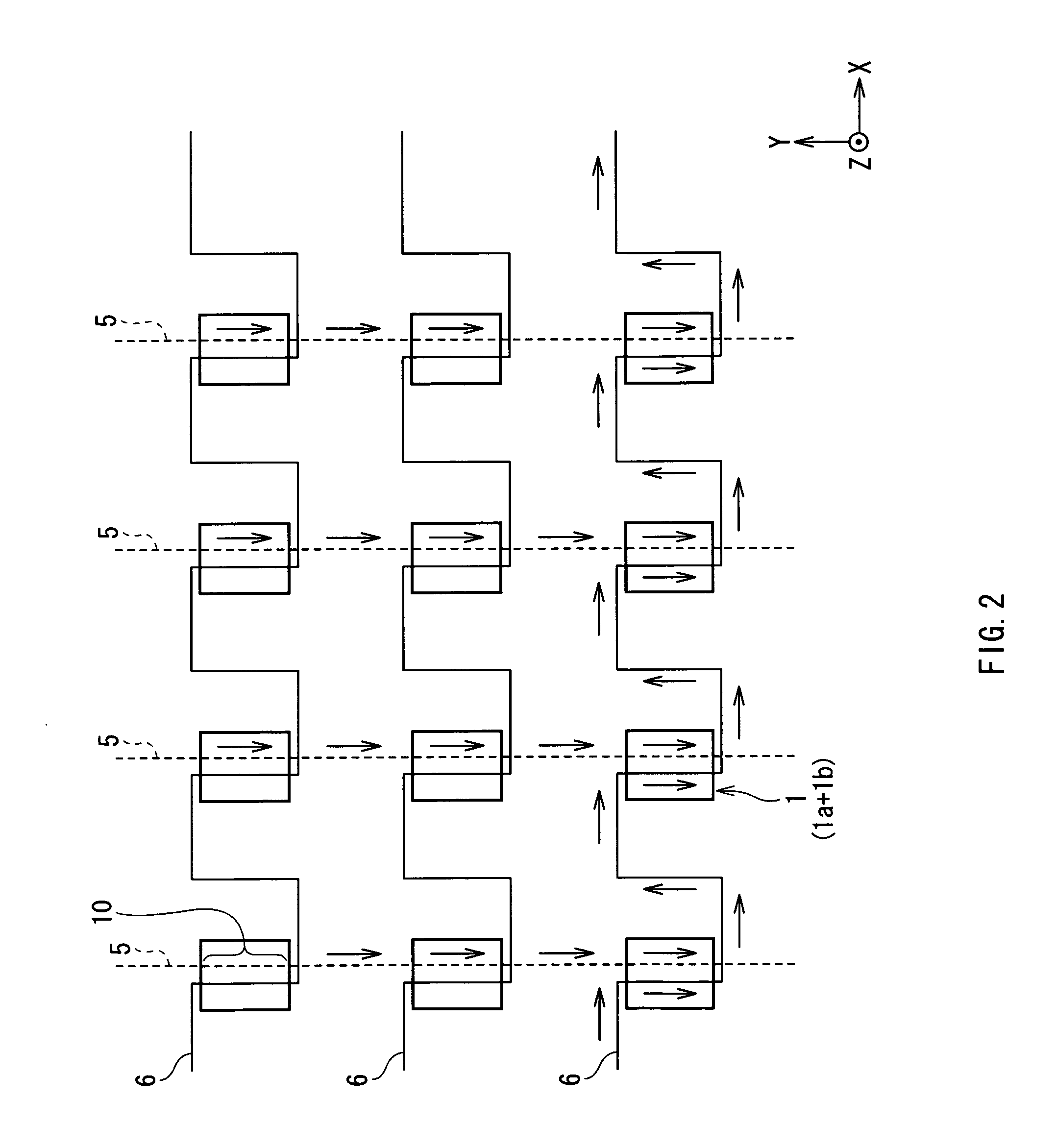
[0087] The memory cell group 54 has a matrix structure in which a number of memory cells 1 each having a pair of tunneling magnetoresistive devices (hereinbelow, called TMR devices) are arranged in a word line direction (X direction) and a bit line direction (Y direction) which are orthogonal to each other. The memory cell 1 is the minimum unit for storing data in the magnetic memory device and is a concrete example corresponding...
second embodiment
[0166] Referring to FIGS. 31 to 35A and 35B, a magnetic memory device of a second embodiment of the invention will now be described.
[0167]FIG. 31 shows a sectional configuration of the memory cell 1H in the magnetic memory device of the embodiment and corresponds to FIG. 5 of the first embodiment. FIG. 32 is an enlarged perspective view of the memory cell 1H and corresponds to FIG. 4. FIG. 33 shows a planar configuration of a magnetic memory device of the modification and corresponds to FIG. 3. In FIGS. 31 to 33, the same reference numerals are designated to the same parts substantially the same as components shown in FIGS. 3 to 5.
[0168] In the following description, the configuration of the magnetic memory device of the second embodiment will be described mainly with respect to the points different from those of the first embodiment, and the other description will be properly omitted.
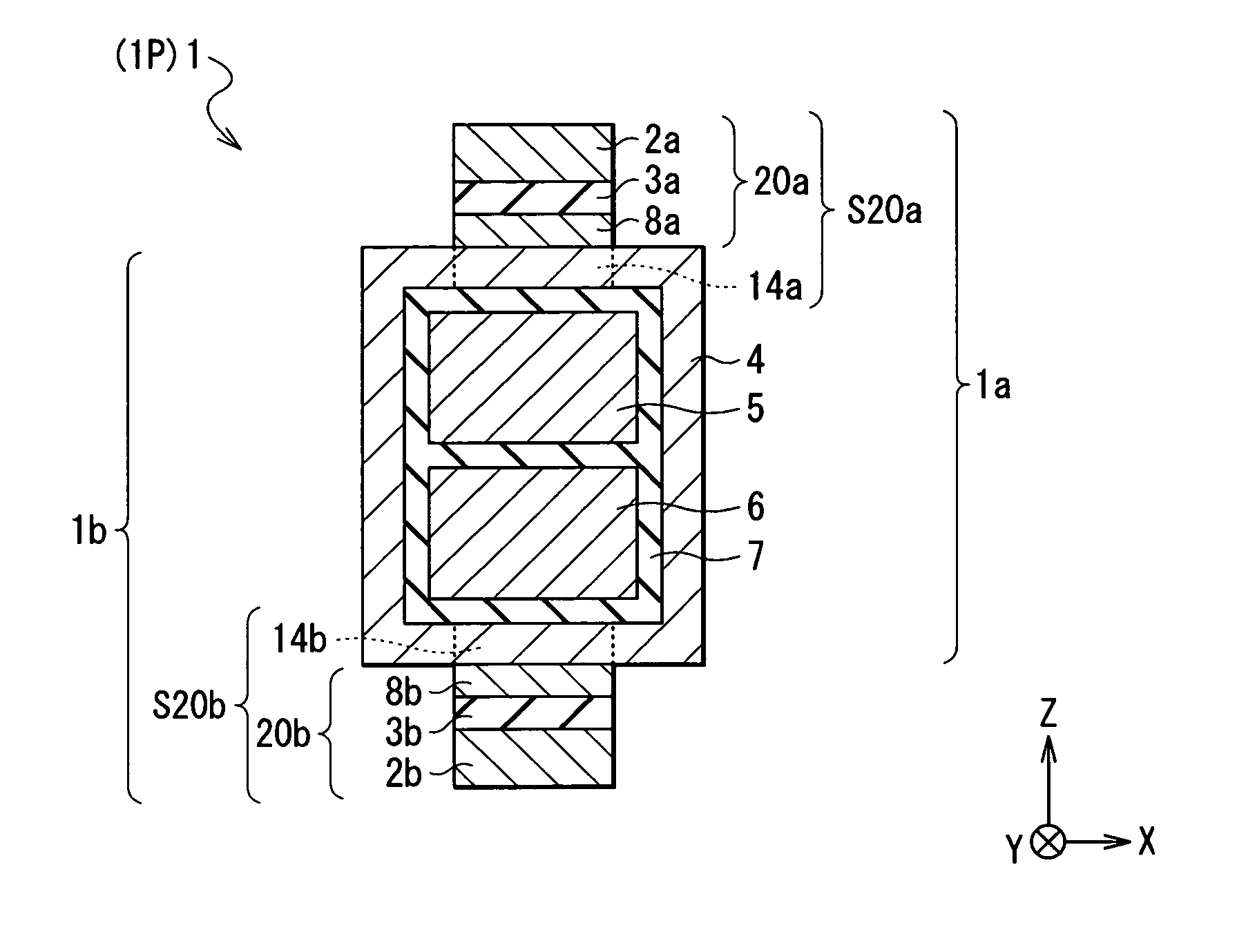
[0169] In the memory cell 1P of the first embodiment, the write word line 6 and the write bit li...
third embodiment
[0175] Referring to FIG. 36A, a magnetic memory device of a third embodiment of the invention will now be described.
[0176]FIG. 36A shows a sectional configuration of a memory cell 121P in the magnetic memory device of the embodiment and corresponds to FIG. 5 of the first embodiment. In FIG. 36A, the same reference numerals are designated to the same parts substantially the same as components shown in FIG. 5.
[0177] In the following description, the confignration of the magnetic memory device of the third embodiment and a method of manufacturing the magnetic memory device will be described mainly with respect to the points different from the first embodiment, and the other description will be properly omitted.
[0178] In the memory cell 1 in the magnetic memory device of the first embodiment, the magneto-sensitive layer is constructed by the connection parts 14a and 14b and the second magnetic layers 8a and 8b which are magnetically exchange-coupled to each other. The connection part...
PUM
 Abstract
Description
Claims
Application Information
 - R&D
- Intellectual Property
- Life Sciences
- Materials
- Tech Scout
- Unparalleled Data Quality
- Higher Quality Content
- 60% Fewer Hallucinations
Browse by: Latest US Patents, China's latest patents, Technical Efficacy Thesaurus, Application Domain, Technology Topic, Popular Technical Reports.
© 2025 PatSnap. All rights reserved.Legal|Privacy policy|Modern Slavery Act Transparency Statement|Sitemap|About US| Contact US: help@patsnap.com


