Recovery of platinum group metals

a platinum group metal and recovery technology, applied in the field of platinum group metal recovery, can solve the problems of uneconomic smelting operations, high cost and lower recoveries, and limitations of the conventional processing route of pgms

Inactive Publication Date: 2007-02-01
LONMIN
View PDF3 Cites 20 Cited by
  • Summary
  • Abstract
  • Description
  • Claims
  • Application Information

AI Technical Summary

Benefits of technology

[0017] The non-selective precipitation of the PGM values and base metals in step a) is preferably carried out by controlled reduction of the pH of the pregnant solution or leachate to within the range of about 0 to about 5, preferably about 1 to about 3, in particular about 2.
[0018] In one embodiment of the invention, the selective leaching in step b) is a pressure leaching step in which the PGM values remain in the residue. The PGM values are typically recovered from the residue by a fusion step or a further leach step to produce a concentrate rich in PGM values. The base metals are recovered from the leach solution, preferably through precipitation. Alteratively, the pressure leaching step may be carried out by first carrying out a caustic leach followed by an acid leach, in which case the PGM values may be recovered from the residue by, for example, a reduction leach step to produce a high grade PGM concentrate.

Problems solved by technology
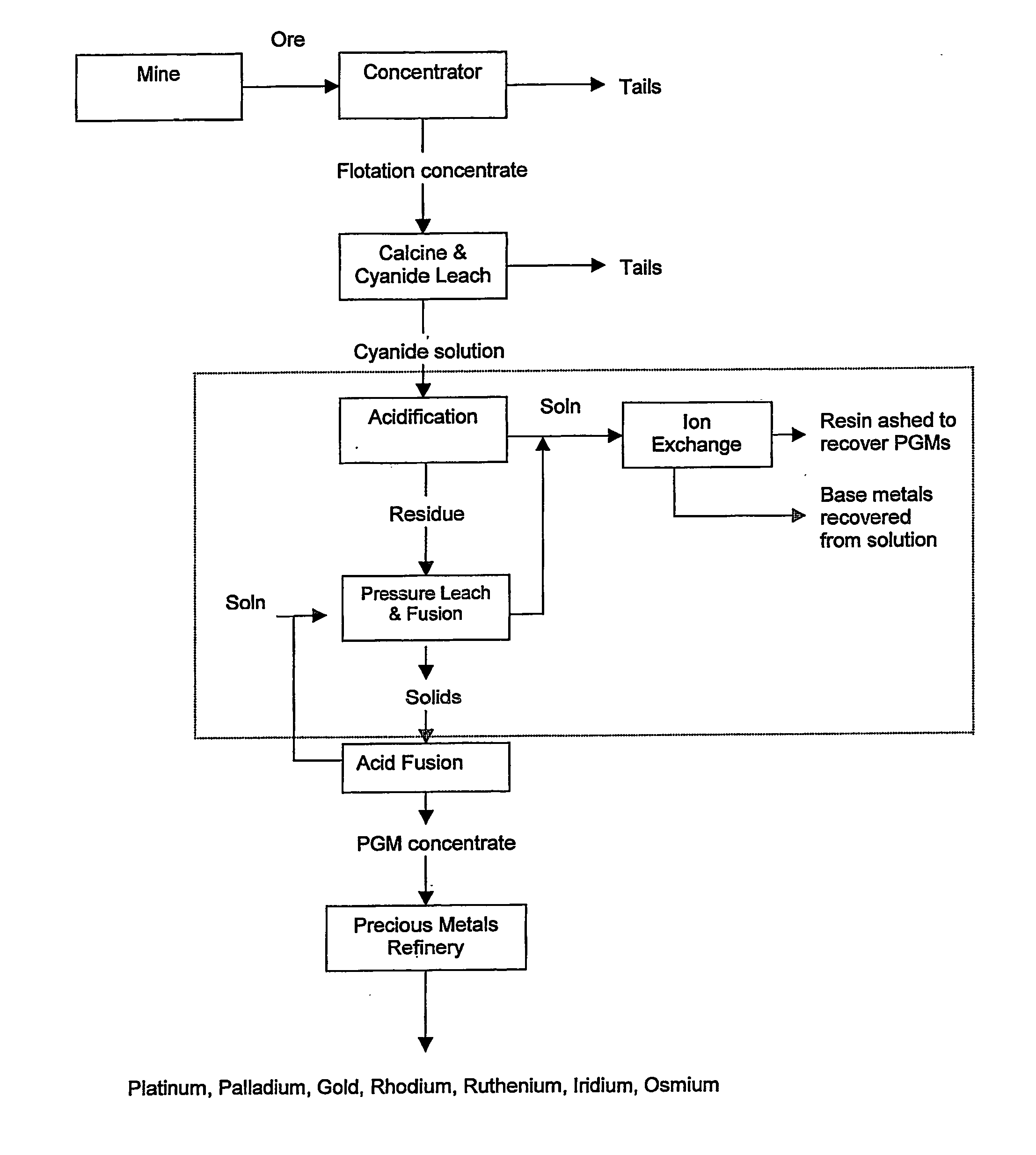
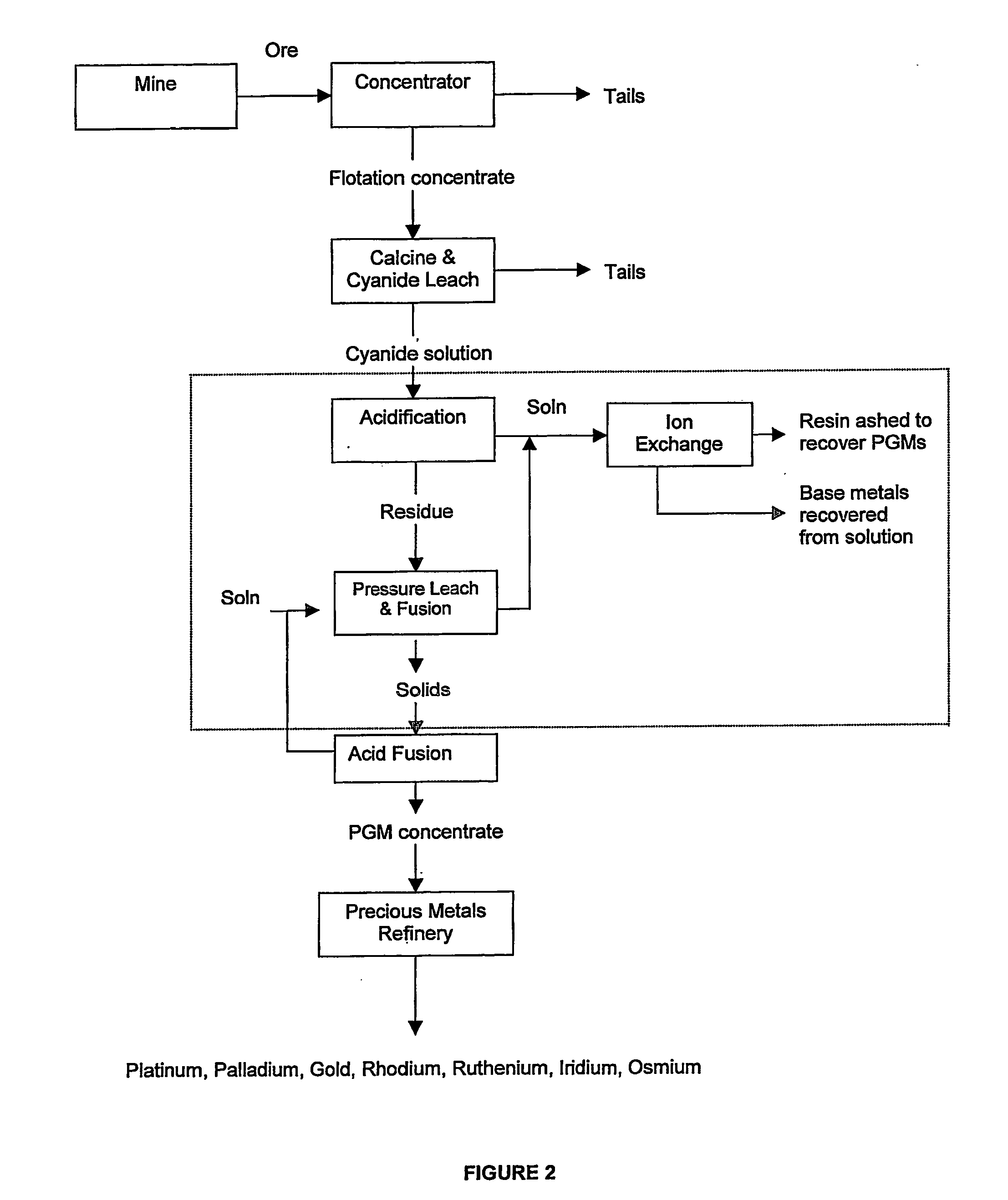
This conventional processing route for PGMs has its limitations.
However, ores that have been oxidised produce greater amounts of flotation concentrates to achieve the same PGM recoveries and this can lead to uneconomic smelting operations.
Concentrates containing relatively high levels of chromite also adversely affect smelting operations, resulting in high costs and lower recoveries.
The erection of new smelters to process PGM containing flotation concentrates has been significantly curtailed in recent years and has all but now been stopped due to very strict environmental legislation and prohibitively high capital costs.
This means that any new operation will have to ship flotation concentrates excessively large distances to existing smelters, at high cost, leading to increased metal pipelines.
This leads to on sulphur dioxide (SO2) fixation plants and often with no revenue return.

Method used


Image

  • Recovery of platinum group metals
  • Recovery of platinum group metals
  • Recovery of platinum group metals

Examples


example 1

Precipitation with Sulphide at Raised Temperature

[0065] A test was conducted using NaHS to precipitate value metals from cyanide leachate at a raised temperature.

[0066] A cyanide leach solution was prepared by calcining underground flotation concentrate at 400° C. for 2 hrs in a muffle furnace and then leaching using 0.2% w / w sodium cyanide solution at 60° C. for 48 hrs, maintaining the pH at 9.5 with hydrated lime.

[0067] 115% stoichiometric level of 20% w / v NaHS was added to 200 ml cyanide leach solution. H2SO4 was added to adjust the pH to 1 and the temperature maintained at 90° C. The solution was sampled after 120 minutes.

[0068] The test results are summarised in Table 1. It can be seen that good recoveries were achieved for Pt, Pd, Au, Cu and Co.

TABLE 1Recoveries into Residue using NaHSMetalPtPdAuCuNiCoRecovery97.5%99.7%99.5%99.3%11.8%92.8%

example 2

Precipitation with Sulphide at Ambient Temperature

[0069] A second series of tests was conducted on the cyanide leachate using NaHS over a range of pHs at ambient temperature to precipitate the value metals.

[0070] A cyanide leach solution was prepared by calcining a finely ground ‘open cut’ flotation concentrate at 400° C. for 2 hrs in a muffle furnace and then leaching using 0.2% NaCN solution at 60° C. for 48 hrs, maintaining the pH at 9.5.

[0071] 115% stoichiometric level of 20% w / v NaHS solution was added to a series of 200 ml cyanide leach solutions, H2SO4 or NaOH was added to adjust the pH in the range 0.5-11.5. The reaction time was 5 mins.

[0072]FIG. 6 shows that good recoveries were obtained for Cu, Co, Pd and Au at low pH values. The test results have been summarised in Table 2.

TABLE 2Sulphide Precipitation Metal RecoveriesPrecipCuNiCoFePtPdAupH(%)(%)(%)(%)(%)(%)(%)0.599.7711.9895.450.0047.6599.4698.101.599.9731.0292.3971.4238.4431.5586.523.599.752.454.0346.771.200.8615...

example 3

Precipitation using H2O2 and Na2S2O5

[0073] A series of tests was conducted using H2O2 and Na2S2O5 to precipitate the value metals from cyanide solution over a range of pH values.

[0074] A cyanide leach solution was prepared by calcining underground flotation concentrate at 400° C. for 2 hrs in a muffle furnace and then leaching using 0.2% NaCN solution at 60° C. for 48 hrs maintaining the pH at 9.5.

[0075] Hydrogen peroxide (H2O2) was added to the cyanide leach solution in the ratio of 1.5 mg / mg of CNWAD at ambient temperature and sulphuric acid was added to maintain the pH at set points between the ranges of 1-7. The reaction time was 120 min.

[0076] Sodium metabisulphate (Na2S2O5) was then added in the ratio of 6 mg / mg of CNWAD. Sulphuric acid was added to maintain the same pH. Again the reaction time was 120 min.

TABLE 3Metal Recovery with H2O2 and Na2S2O5 TreatmentMetal removed from solution %TestpHPtPdAuCuNiCoH2O20.999.699.64.291.281.199.7Na2S2O51.0048.36.229.04.60Overall99.6...


PUM

PropertyMeasurementUnit
pHaaaaaaaaaa
temperatureaaaaaaaaaa

Abstract

A process of recovering platinum group metals (PGMs) from a pregnant solution or leachate containing PGM values and base metals, typically a cyanide solution or leachate. A non-selective precipitation of the PGM values and base metals to form an insoluble precipitate comprising the PGM values and base metals is followed by selective leaching of the precipitate. The selective leaching forms a leach solution containing the base metals and a residue containing the PGM values, or a leach solution containing the base metals and PGM values and a depleted residue. The base metals are recovered from the leach solution and the PGM values are recovered from the residue or the leach solution, depending on the selective leaching. The non-selective precipitation of the PGM values and base metals is carried out by controlled reduction of the pH of the pregnant solution or leachate to a pH of about 2.

Description

BACKGROUND OF THE INVENTION [0001] This invention relates to a method of recovery of platinum group metals (PGMs) from a solution or leachate containing the PGMs and base metals, and to the production of a PGM concentrate suitable as a feed stock to a PGM refinery. [0002] PGMs usually occur as discrete minerals, as dilute solid solutions in sulphide minerals, or are associated with silicates and / or chromitites. The processing of these materials consists of a combination of several unit operations, which ultimately produce individual PGMs—platinum, palladium, rhodium, ruthenium, iridium and osmium—plus gold and silver. [0003] Currently PGM ores containing varying amounts of base metals, such as copper, nickel and cobalt, are crushed, milled and floated in flotation cells using reagents typically used for the recovery of base metal sulphides, to produce a low grade PGM concentrate. This flotation concentrate is dried and then smelted in an electric arc furnace where the PGMs are colle...

Claims


Application Information

Patent Timeline
Patent Type & Authority Applications(United States)
IPC IPC(8): C22B11/00C22BC22B3/42C22B3/44C22B11/08C22B15/00
CPCC22B3/42C22B3/44C22B15/0093C22B11/08C22B15/0076C22B11/04Y02P10/20
Inventor BAX, ALANDUNN, GREENVIL MARQUISLEWINS, JOHN DEREK
Owner LONMIN
Why Eureka
Try Eureka