Actuating drive and emergency energy supply device

a technology of actuating drive and emergency energy supply, which is applied in the direction of motor/generator/converter stopper, dynamo-electric converter control, instruments, etc., can solve the problems of increasing the cost of energy storage, the performance of the wind power installation may be adjusted to the wind speed, and the rotor hub is not suitable for conventional lead-acid or lead-gel accumulators, etc., to achieve optimal availability of actuating drive, increase internal resistance, and maintenance according demand

Inactive Publication Date: 2007-02-01
BOSCH REXROTH AG
View PDF13 Cites 51 Cited by
  • Summary
  • Abstract
  • Description
  • Claims
  • Application Information

AI Technical Summary

Benefits of technology

[0027] Another embodiment provides determining the internal resistance of an accumulator unit. For instance, it is possible to determine the internal resistance of an accumulator unit, among others, from the accumulator voltage, during a discharging process via a known resistor. The internal resistance permits making a meaningful estimate of the working capacity of the accumulator unit, and thus also of the emergency energy supply device. An increased internal resistance is also a measure of the aging of the accumulator unit. Therefore, a maintenance indication is preferably activated if the internal resistance is greater than a first threshold value. In this way, maintenance according to demand is assured, and so is an optimal availability of the actuating drive.
[0028] If an accumulator unit is shunted out if its internal resistance exceeds a secon

Problems solved by technology

Because of that, the performance of the wind power installation may be adjusted to the wind speed, and may be limited, if necessary, in response to high wind speeds.
The disadvantage with the conventional rotor blade actuating drive is that the energy store of the emergency supply has to be designed for a high voltage, especially for a high charging voltage that corresponds to the link operating voltage.
The costs of the energy store rise with the number of accumulators/capacitors connected in series.
Conventional lead-acid or lead-gel accumulators are little suited to be positioned in the rotating rotor hub, since they have a high requirement for space and a large weight.
In addition, lead-acid or lead-gel accumulators are difficu

Method used


Image

  • Actuating drive and emergency energy supply device
  • Actuating drive and emergency energy supply device
  • Actuating drive and emergency energy supply device

Examples


Embodiment Construction

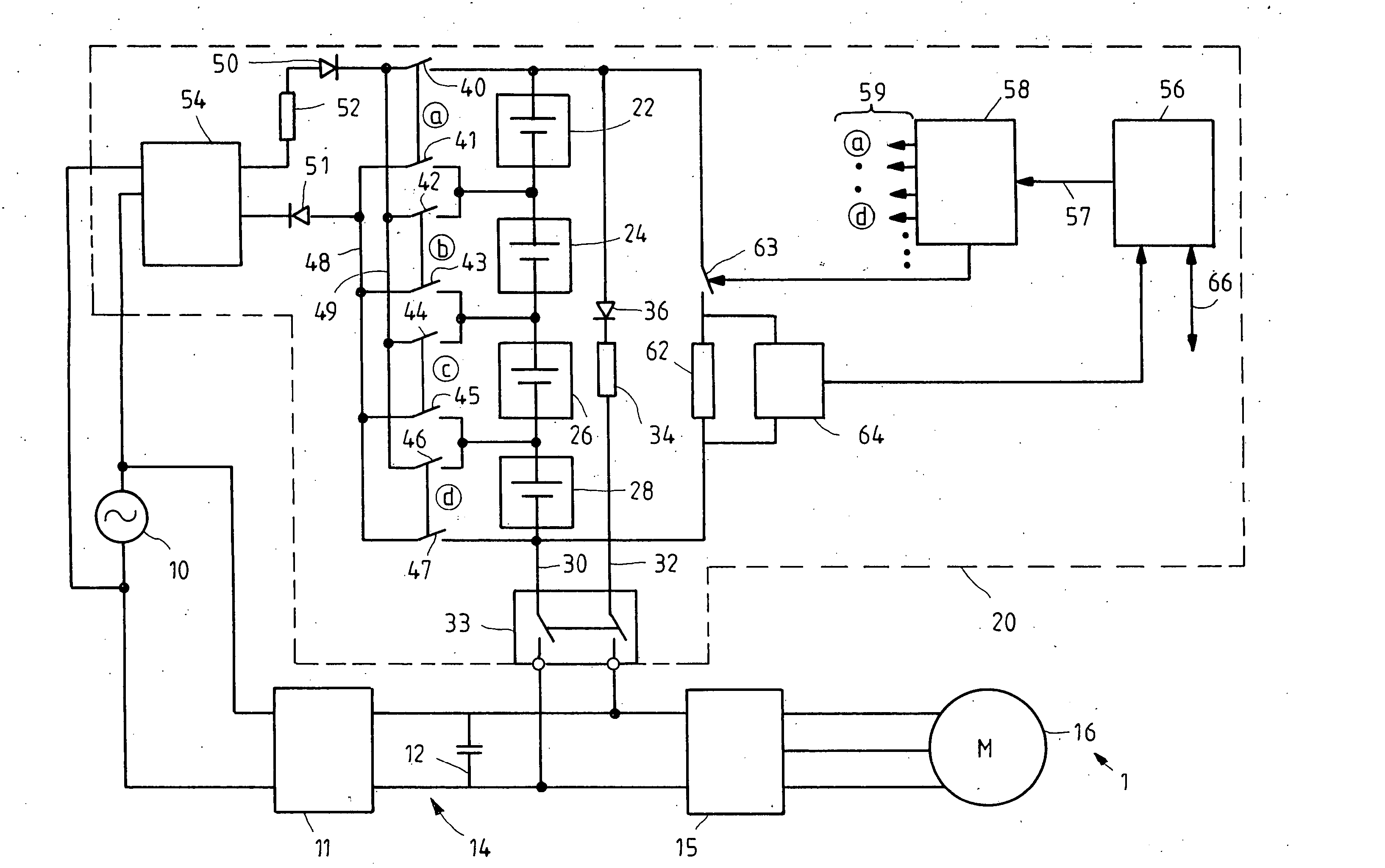
[0033]FIG. 1 shows a simplified block diagram of a three-phase a.c. power actuating driveO 1, for use as a rotor blade adjustment drive in a wind power installation. An a.c. mains system 10 supplies a rectifier 11, which, in turn, feeds a link capacitor 12 of a direct voltage link 14 with direct voltage. A d.c.-to-a.c. inverter 15 takes electrical energy from link 14, in order to drive a three-phase a.c. motor 16. D.c.-to-a.c. inverter 15 is activated by a control unit (not shown), so as to specify the three-phase current frequency with which motor 16 is driven. Rectifier 11, link 14 and d.c.-to-a.c. inverter 15 and the control unit mentioned form a frequency converter for driving motor 16.

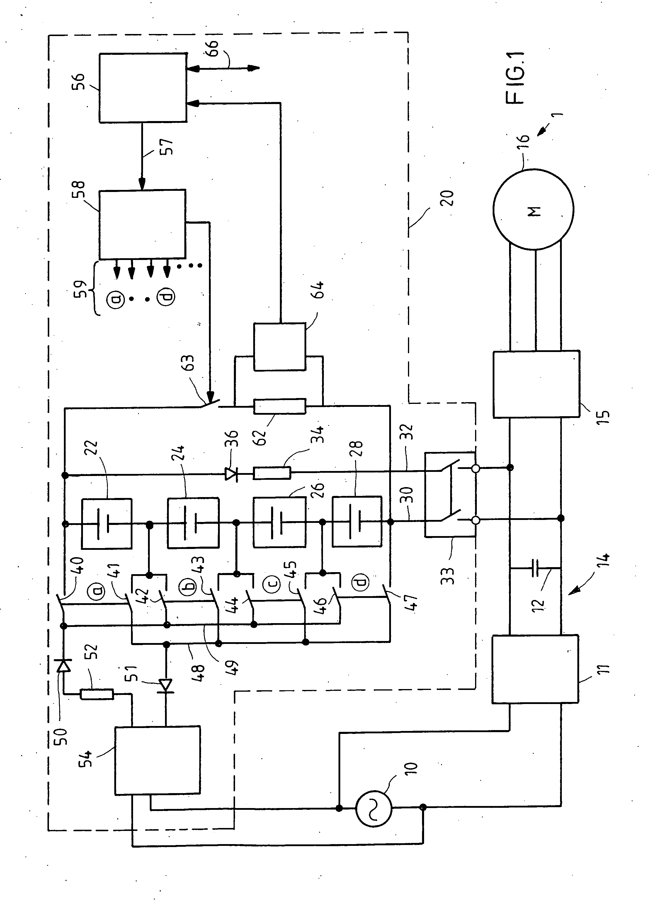
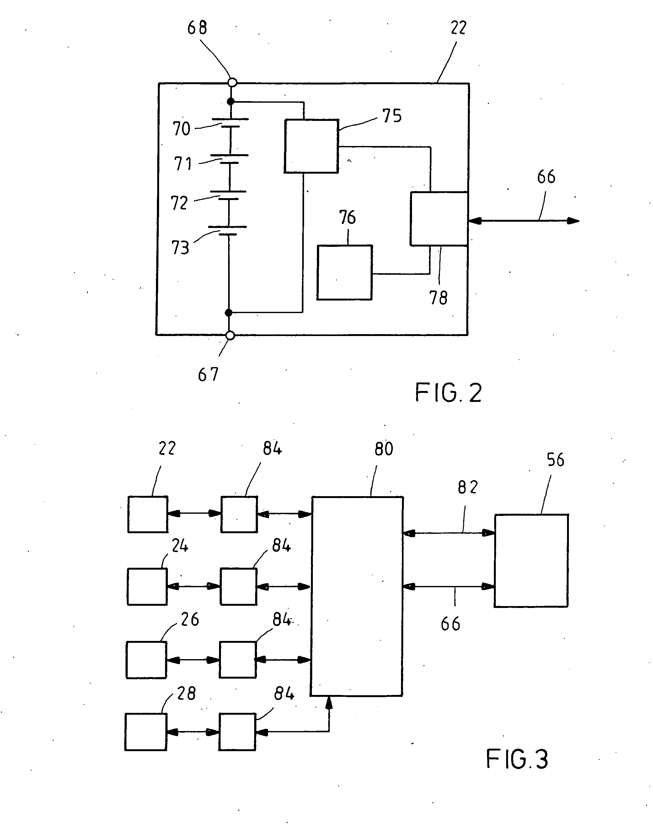
[0034] An emergency energy supply device 20 is connected to direct voltage link 14. An electrical energy store is formed from eight accumulator units connected in series. Each of the accumulator units has a nominal voltage of 36 Volt. The energy store accordingly delivers a voltage of 288 Volt. D...


PUM


Abstract

An actuating drive for a rotor blade in a wind power installation is provided with an electric motor and a frequency converter which has a rectifier that is to be fed from a power supply system, a link connected to the rectifier, and a d.c.-to-a.c. inverter for feeding the motor, the link carrying a specified nominal operating voltage in a network-fed normal operation of the frequency converter. Furthermore, an auxiliary energy supply device is provided that is connected to the link. The auxiliary energy supply device includes and energy store which makes available a support voltage that amounts to less than 80% of the nominal operating voltage of the link. A diode is connected between the energy store and the link, and is arranged, with regard to its forward direction, in such a way that it feeds a support voltage from the energy store into the link if the link voltage falls below the support voltage. The diode prevents a current flow between the energy store and the link if the link voltage is greater than the support voltage. A charging device for the energy store has a lower charging voltage than the nominal operating voltage of the link.

Description

FIELD OF THE INVENTION [0001] The present invention relates to an actuating drive for a rotor blade of a wind power installation. Furthermore, the present invention relates to an emergency energy supply device for supplying an electrical actuating drive of a wind power installation in emergency operation. BACKGROUND INFORMATION [0002] Wind power installations of high performance are almost exclusively equipped with adjustable rotor blades. Because of that, the performance of the wind power installation may be adjusted to the wind speed, and may be limited, if necessary, in response to high wind speeds. If there is danger of overloading by strong wind, or in order to take the installation out of operation, the rotor blades are rotated into a so-called feathered pitch, in which no driving buoyancy is created on the rotor blades. In part, it is sufficient to put a rotor blade into feathered pitch, in order to brake the wind power installation. Preferably all rotor blades are rotated ou...

Claims


Application Information

Patent Timeline
IPC IPC(8): G05B5/00
CPCF03D7/0224F05B2260/76F05B2260/79F05B2270/1074Y02E10/766H02J9/062Y02B10/72Y02E10/721Y02E10/723H02J7/0024Y02B10/70Y02E10/72Y02E10/76
Inventor KUNKEL, STEFFENHERRMANN, KARL-GUNTERHORNING, MICHAELKOBELBAUER, BERNODANTLGRABER, JORGBECKER, STEPHANNEIDLEIN, GUNTHERSCHNURR, BERND
Owner BOSCH REXROTH AG
Why Eureka
Try Eureka