
Apparatuses and systems for monitoring fouling of aqueous systems including enhanced heat exchanger tubes

a technology of aqueous systems and apparatus, applied in the direction of heat measurement, instruments, heat treatment water, etc., can solve the problems of contaminant entering the system and fouling is an extremely complex phenomenon, and achieve the effects of preventing excessive heat transfer loss, rapid foulant detection and characterization, and improving performance-based monitoring control

Active Publication Date: 2007-02-01
SOLENIS TECH CAYMAN
View PDF50 Cites 20 Cited by
  • Summary
  • Abstract
  • Description
  • Claims
  • Application Information

AI Technical Summary

Benefits of technology

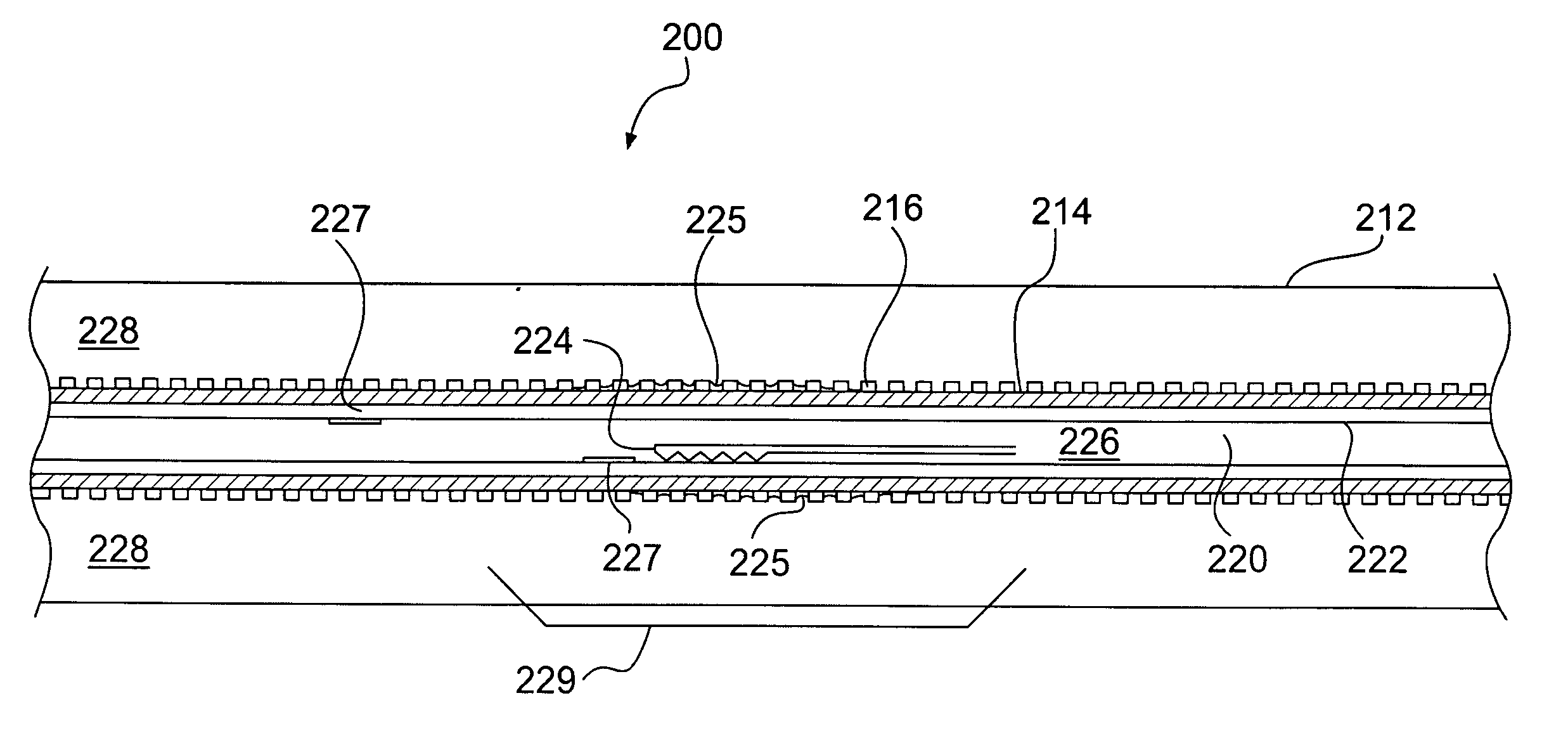
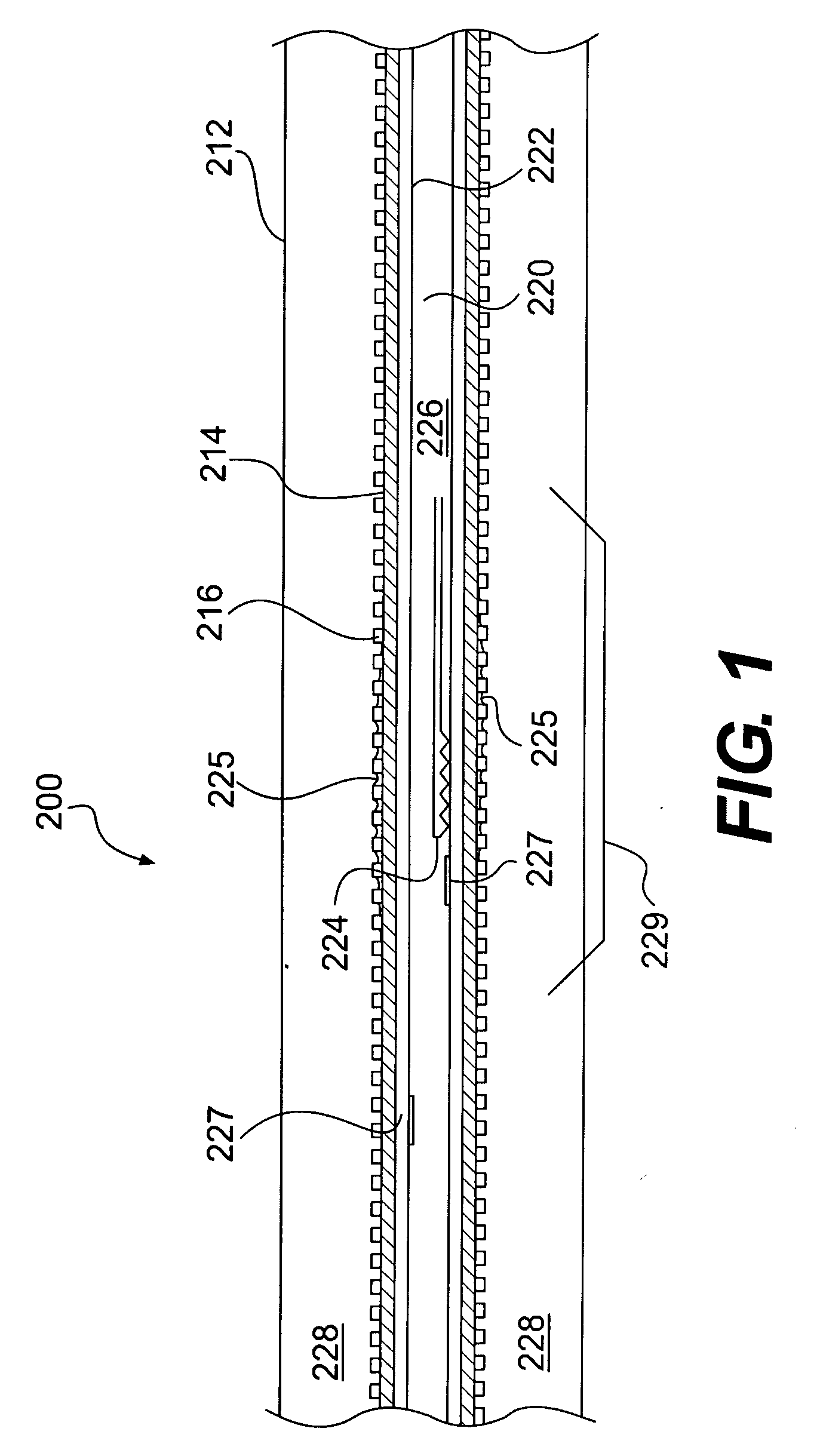
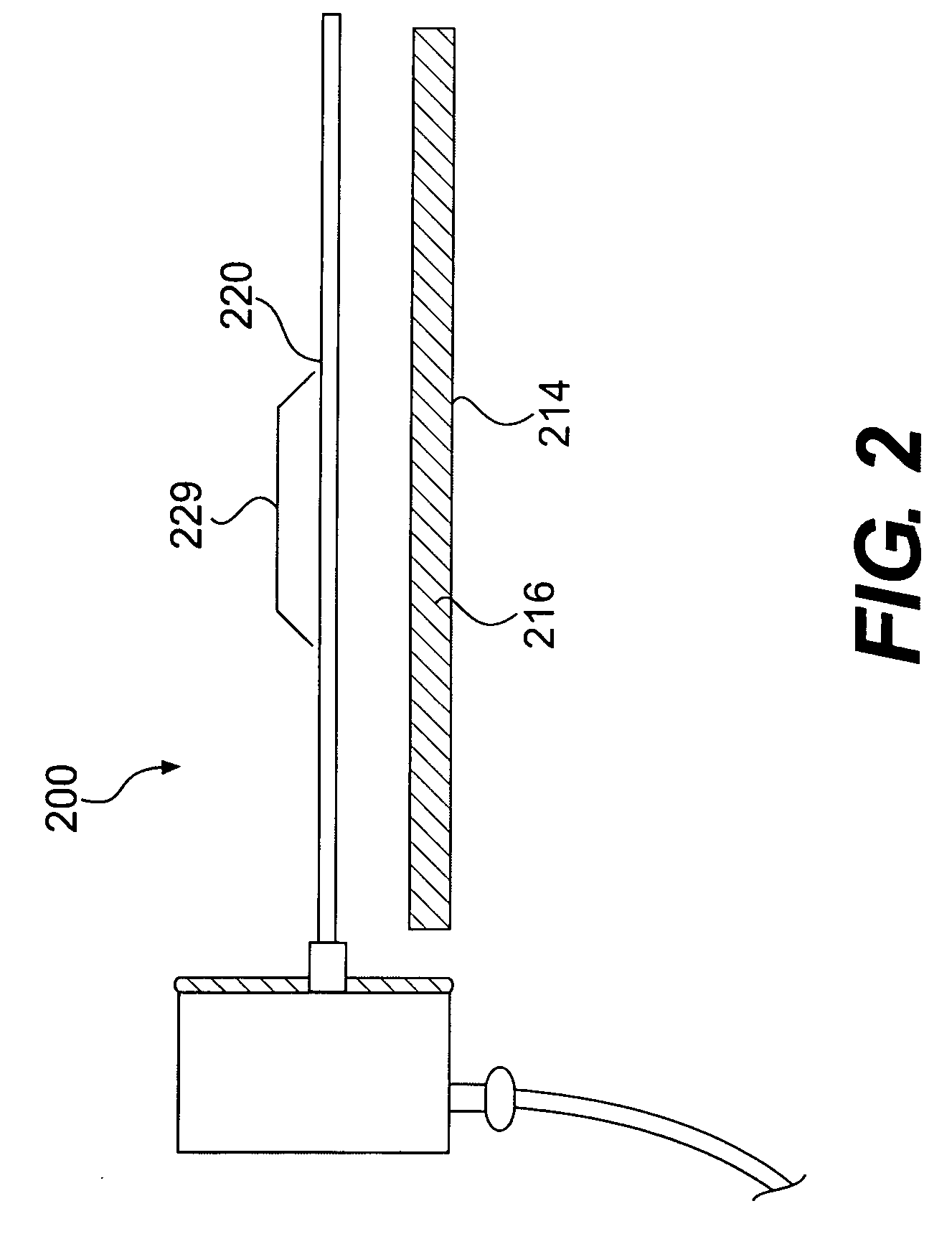
[0012] Knowing that biofouling occurs more rapidly on non-smooth surfaces than on smooth surfaces, the present inventors have realized that biofouling in an aqueous system including enhanced heat exchanger tubes could be detected more quickly if the heater rod of a heat transfer test assembly such as the '945 patent and '587 patent test assemblies, which have a smooth outer surface, were provided with an element having a non-smooth (i.e., enhanced) surface for collecting biofilm, wherein the enhanced surface is the inner surface of the annular test conduit. In aqueous systems having heat exchanger tubes with non-smooth (“enhanced”) inner bores, earlier detection of biofouling could allow one to determine biofilm formation prior to excessive build-up of biofilm on the heat exchanger tubes. The inventors further recognized that using an enhanced rod as the inner surface of the annular test conduit provides a less confining environment for modeling than the actual heat exchanger tube with its internal enhancements. In addition, using an enhanced rod as the inner surface of the annular test conduit provides the advantage of being able to visually observe the deposition and cleaning process.
[0024] A test assembly including an enhanced rod as described above incorporated in a side stream heat transfer test section can be utilized to detect fouling occurrence rapidly as well as tracking the clean-up improvements to completion. This capability can provide enhancements to performance-based monitoring control for cooling waters. If used in conjunction with a smooth bore tube monitor (i.e., a monitor with a smooth rod as disclosed in U.S. Pat. Nos. 4,339,945, Re. 33,346, 4,346,587 and Re. 33,468) in parallel, an enhanced tube monitor (i.e., a monitor with an enhanced rod) can allow for categorization of the type of foulant that is detected. Thus, the appropriate mitigation method and chemistry selection can be implemented.
[0025] The monitoring capabilities of systems employing the disclosed enhanced tube test assembly promote rapid foulant detection and characterization, and allow for proactive corrective treatment measures that can prevent excessive heat transfer losses and the development of localized corrosion. This monitoring and foulant control technology should allow for a broader acceptance and applicability of the use of enhanced heat exchanger tubes in the cooling water industry. Although the devices and systems described herein are generally described in the context of an aqueous heat transfer fluid circulating through a heat exchanger, it will be understood that the devices and systems are applicable to any heat transfer fluid including hydrocarbons, euthetic salt solutions and the like, circulating through a vessel in heat transfer relationship where fouling is a problem.

Problems solved by technology

Many of the foulant components found in water systems originate with the incoming supply, but some contaminants enter the system from the local environment or from process contamination.
Fouling is an extremely complex phenomenon.

Method used


Image

  • Apparatuses and systems for monitoring fouling of aqueous systems including enhanced heat exchanger tubes
  • Apparatuses and systems for monitoring fouling of aqueous systems including enhanced heat exchanger tubes
  • Apparatuses and systems for monitoring fouling of aqueous systems including enhanced heat exchanger tubes

Examples


example 1

Inorganic Fouling

[0058] Initially, tests were conducted to determine the relative fouling tendency of enhanced tubes versus smooth tubes in the presence of inorganic foulants, such as calcium carbonate and calcium phosphate in the absence of biomass. An organic deposit and corrosion control additive blend was also present in the cooling water. The chemistry under which the tests were performed is listed in Table 2. Under those conditions, with a velocity of 1.6 m / sec. (5 ft / sec.) and a surface temperature of 65.5° C. (150° F.) on the smooth rod, fouling occurred within 7 days (standard water chemistry concentrated 5 times). At a lower surface temperature of 54.4° C. (130° F.) fouling of the smooth rod was not observed until the 14th day wherein the standard water chemistry was concentrated to 9.0 times with an additional 1.5 mg / L of orthophosphate present. The enhanced rod required an increase in skin temperature to 63° C. (145° F.) in conjunction with concentrating the standard wa...

example 2

Organic Fouling (Biofouling)

[0059] Further experiments were focused on fouling associated with biomass and to discover an efficient means to remove accumulated biomass. A blank biofouling run was performed where the cooling water was inoculated with pseudomonas aerigenosa (ATCC 27853), a known slime forming aerobic bacterium. Nutrient broth was added to the tower daily at a dose of 50 mg / L. Chemistry and data associated with this test run are provided in Table 3. Although biofouling was observable by the naked eye by the seventh day into the run, it was actually detected as an increasing trend on the third and fifth day by the enhanced tube and smooth tube respectively. The enhanced rod fouled at a linear rate of 0.439 m2-° K / Watt-sec., while the smooth rod fouled at a rate of 0.097 m2-° K / Watt-sec. as illustrated in FIG. 7.

TABLE 3Blank Biofouling Run - Water Chemistry and DatapH7.0“P” Alkalinity, mg / L as CaCO30Carbonate, mg / L as CaCO30Total Alkalinity, mg / L as CaCO354Bicarbonate...

example 3

Subsequent Biofouling Testing

[0060] Subsequent tests were run until the enhanced rod flutes (grooves between adjacent ribs) were filled with foulants, then various chemistries were employed to clean the rod. The smooth rod never did foul as fast as the enhanced rod, nor did it foul to the extent seen with the enhanced rod.

[0061] As illustrated by the preceding disclosure, an enhanced rod incorporated in a side stream heat transfer test section can be employed to detect fouling occurrence rapidly as well as tracking the clean-up improvements to completion. This capability can provide enhancements to performance-based monitoring control for cooling waters. If used in conjunction with a smooth bore tube monitor (i.e., a monitor with a smooth rod) in parallel, an enhanced tube monitor (i.e., a monitor with an enhanced rod) can allow for categorization of the type of foulant that is detected. Thus, the appropriate mitigation method and chemistry selection can be implemented.

[0062] The...


PUM


Abstract

Heat transfer test assemblies for monitoring and recording fouling of aqueous systems are disclosed. The heat transfer test assemblies include an outer tube member, a heating rod positioned within the outer tube member, a ribbed tube sleeve fitted over the heating rod and thermocouples for sensing the wall temperature of heating rod. The disclosed heat transfer test assemblies enable improved monitoring of systems employing enhanced heat exchanger tubes. Monitoring and recording apparatuses including the heat transfer test assemblies are also disclosed.

Description

[0001] This application claims the benefit of U.S. provisional application No. 60 / 666,750, filed on Mar. 31, 2005 and entitled Heat Transfer Test Assembly for an Apparatus for Monitoring Fouling of Aqueous Systems, the entire disclosure of which is incorporated herein by reference.BACKGROUND [0002] The chemical water treatment industry has historically been involved with reducing or inhibiting the inherent scale forming or fouling tendencies of natural waters associated with large industrial cooling water systems. Many of the foulant components found in water systems originate with the incoming supply, but some contaminants enter the system from the local environment or from process contamination. [0003] Fouling is an extremely complex phenomenon. Fouling of a heat transfer surface is defined as the deposition on a surface of any material which increased the resistance to heat transfer. The fouling tendency of a fluid in contact with a heat transfer surface is a function of many var...

Claims


Application Information

Patent Timeline
IPC IPC(8): G01K7/00G01K1/14G01N25/00
CPCA61L2/16C02F1/4674C02F1/76C02F1/766C02F2103/023G01N17/008C02F2209/04C02F2209/06C02F2303/20C02F2305/04F28F19/00C02F2201/003
Inventor HAYS, GEORGE F.HOERNLE, ERIC P.
Owner SOLENIS TECH CAYMAN
Learn More