

Method for producing electrochemical capacitor electrode
- Summary
- Abstract
- Description
- Claims
- Application Information
AI Technical Summary
Benefits of technology
Problems solved by technology
Method used
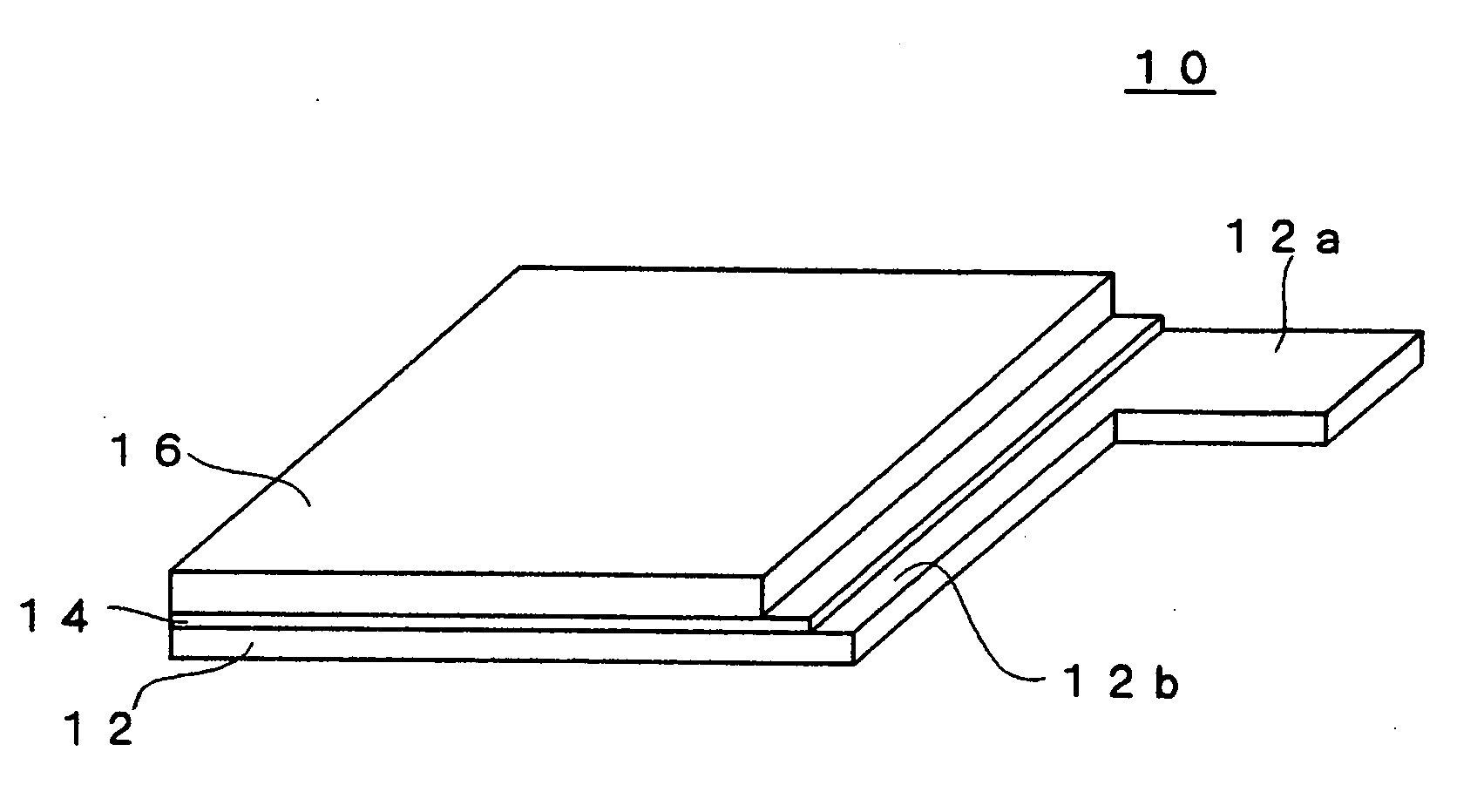
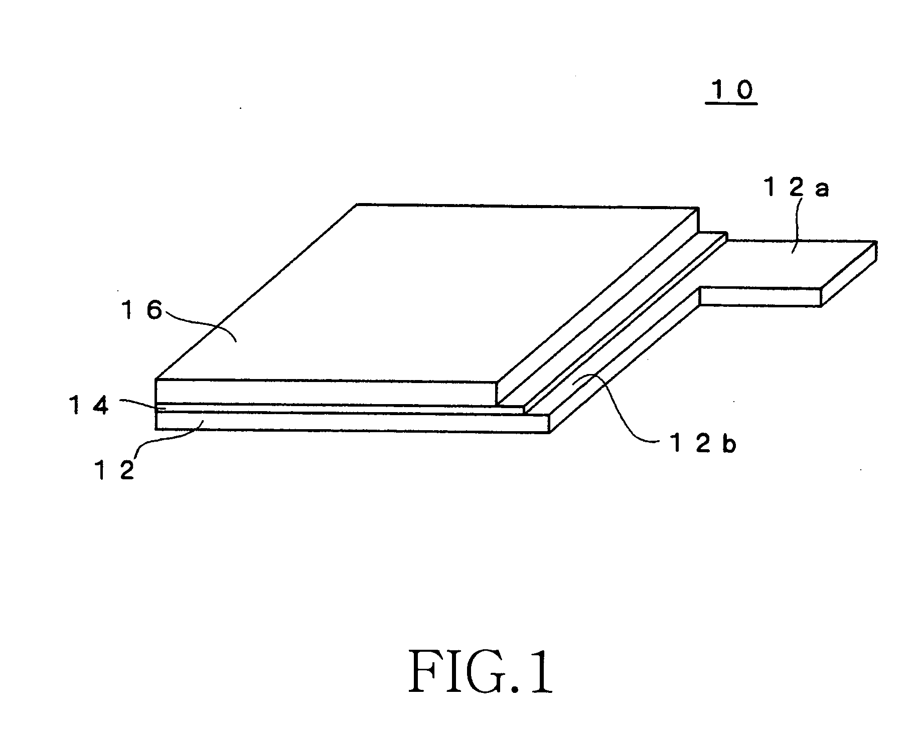
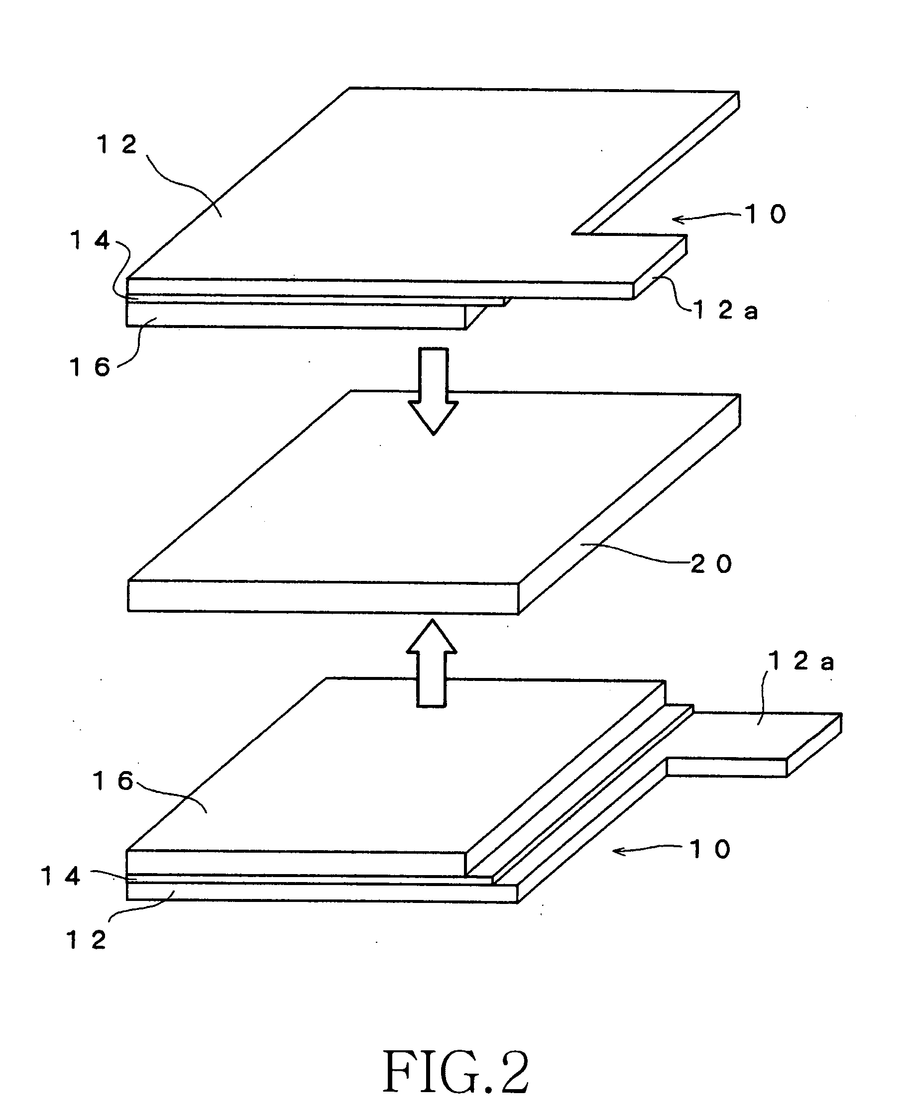
Image

Examples
working example 1
[0084] The electroconductive particles used in the coating solution X for the undercoat layer were prepared by mixing 33 parts by weight of acetylene black (product name: Denka Black manufactured by Denki Kagaku Kogyo) and 33 parts by weight of graphite for 15 minutes by using a planetary disperser. Further added to the entire weight of the mixture were 35 parts by weight of fluorine rubber (product name: Viton-GF manufactured by DuPont Dow Elastomer) as a binder and 140 parts by weight of methylisobutyl ketone (MIBK) as a solvent (good solvent), and the mixture was kneaded for 45 minutes using a planetary disperser.
[0085] Subsequently added were 119 parts by weight of the above-mentioned fluorine rubber as a binder, 1,543 parts by weight of MIBK (good solvent) as a solvent, and 297 parts by weight of propylene carbonate (poor solvent). The mixture was stirred for four hours and a coating solution X for the undercoat layer was prepared. The weight ratio (P / B) of the electroconducti...
working example 2
[0095] The electrode sheet sample of working example 2 was manufactured in the same manner as in working example 1 except that the amount in which fluorine rubber was added to the mixture was set to 229 parts by weight, and the amount of solvent was changed so that the viscosity of the coating solution X for the undercoat layer was 0.37 Pa·s in the preparation of the coating solution X for the undercoat layer of working example 1.
[0096] Therefore, in working example 2, the weight ratio (P / B) of the electroconductive particles (P) and the binder (B) included in the coating solution X for the undercoat layer was 20 / 80.
working example 3
[0097] The electrode sheet sample of working example 3 was manufactured in the same manner as in working example 1 except that the amount in which fluorine rubber was added to the mixture was set to 64 parts by weight, and the amount of solvent was changed so that the viscosity of the coating solution X for the undercoat layer was 0.37 Pa·s in the preparation of the coating solution X for the undercoat layer of working example 1.
[0098] Therefore, in working example 3, the weight ratio (P / B) of the electroconductive particles (P) and the binder (B) included in the coating solution X for the undercoat layer was 40 / 60.
PUM
| Property | Measurement | Unit |
|---|---|---|
| Dynamic viscosity | aaaaa | aaaaa |
| Dynamic viscosity | aaaaa | aaaaa |
| Fraction | aaaaa | aaaaa |
Abstract
Description
Claims
Application Information