Ultrahydrophobic substrates

a technology of hydrophobic substrates and substrates, applied in the field of ultrahydrophobic substrates, can solve the problems of expensive and complicated processing techniques, limited methods, etc., and achieve the effects of increasing the hydrophobicity of the surface, and increasing the surface roughness

Active Publication Date: 2007-02-01
CLEMSON UNIVERSITY
View PDF5 Cites 91 Cited by
  • Summary
  • Abstract
  • Description
  • Claims
  • Application Information

AI Technical Summary

Benefits of technology

[0007] In one embodiment, the invention is directed to a method for modifying the surface of a substrate. The method can include, for instance, grafting a plurality of structures to a substrate surface. The addition of the structures to the substrate surface can increase the surface roughness of the substrate. The method can also include grafting a hydrophobic material to the substrate surface. The combination of the increased surface roughness and the increased hydrophobicity of the surface can provide an ultrahydrophobic surface to the substrate. In particular, the modified substrate surface can describe both a water contact angle and a water receding angle of greater than about 150°.

Problems solved by technology

While such methods have shown capability for creating a rough surface on particular materials, the methods are fairly limited in application and also require expensive and complicated processing techniques.

Method used


Image

  • Ultrahydrophobic substrates
  • Ultrahydrophobic substrates
  • Ultrahydrophobic substrates

Examples


example 1

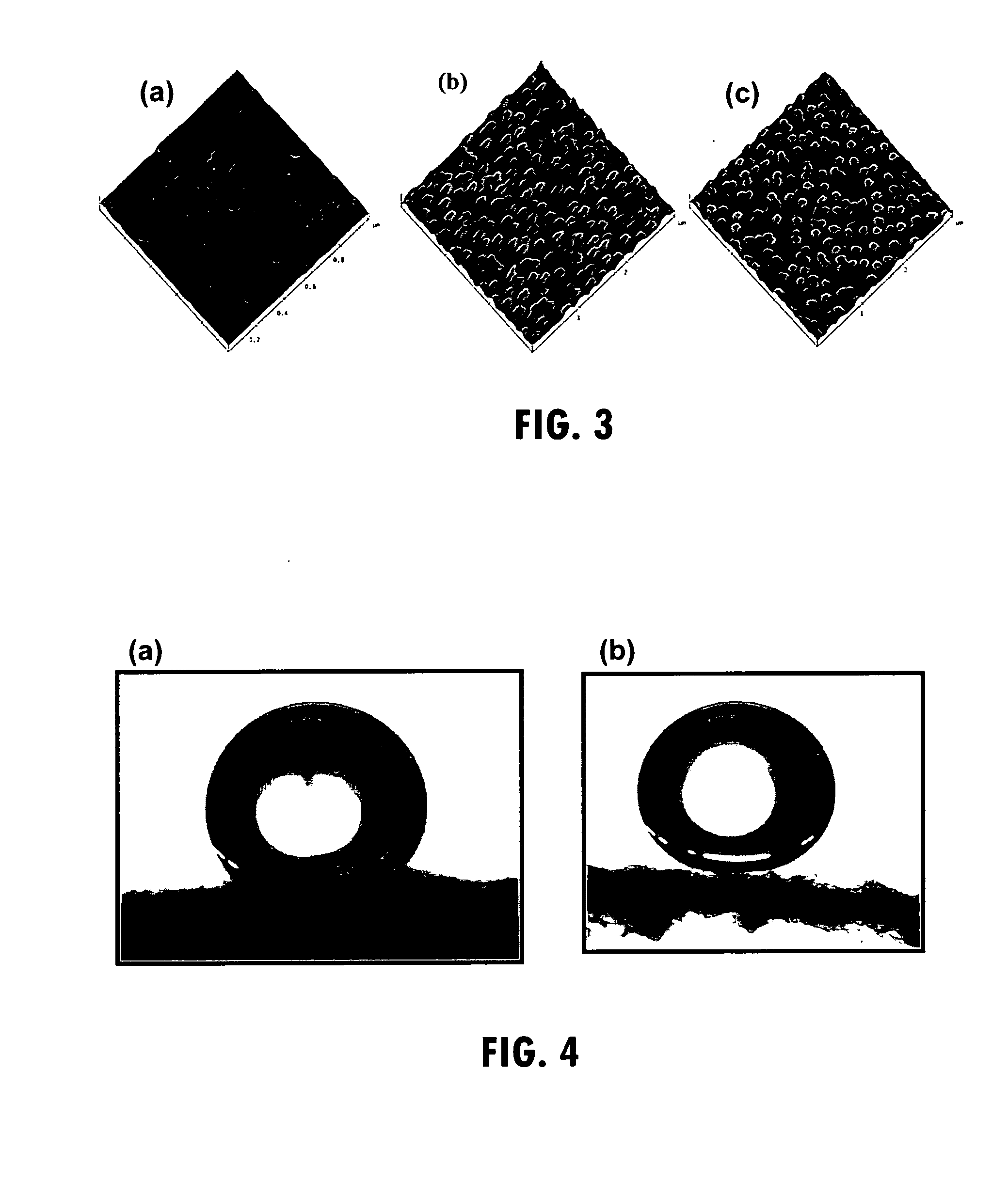
[0066] A 70 / 30 by weight PG MA / PVP (epoxidized poly(glycidyl methacrylate) / poly(2-vinylpyridine)) solution from MEK (0.2 wt %) was formed and applied to a silicon wafer. The modified substrate was cured at 110° C. for 10 minutes to aid self cross-linking of the epoxy groups of PGMA. An SPM topography image of a 1 μm×1 μm area of the silicon substrate coated with the 70 / 30 PGMA / PVP blend is in shown in FIG. 3A.

[0067] Coated substrates were then exposed to a suspension of silver nanoparticles (110 nm-130 nm in diameter) that had been held in deionized water at low ionic strength overnight in order to maintain substantial long-range electrostatic repulsion between particles and consequently minimize clustering of the nanoparticles on the surface of the substrates.

[0068] Following adsorption of the nanoparticles to the surface, a further layer of PGMA was applied via dip coating. This layer was cured in the same manner as the first layer. This sandwich layer coating was found to be qu...

example 2

[0071] A polyester fabric was modified according to a process as described above for the silicon wafer of Example 1, except that the polyester fabric was first subjected to plasma discharge in the low intensity mode for 10 minutes in order to activate the surface of the fibers forming the fabric. Following activation, a PVP / PGMA layer, silver nanoparticles, a PGMA layer, and a PS layer were applied to the fabric, as described above. As a control, a second fabric was modified with only the polystyrene layer, and no nanoparticles were applied to the surface. Static contact angle analysis was performed on both fabrics, and results are shown in FIG. 4. The contact angle of the fabric was obtained as 113°±3.6 for the control surface (FIG. 4A) and 157°±3 for PS / nanoparticle multilayer system (FIG. 4B). Increase in the contact angle was believed to be due to the limited contact of water with the PS layer in combination with the effect of the entrapped air between the coated surface and the...


PUM

PropertyMeasurementUnit
distanceaaaaaaaaaa
water receding angleaaaaaaaaaa
sizeaaaaaaaaaa

Abstract

Disclosed is a process for modification of a substrate so as to form an ultrahydrophobic surface on the substrate. Also disclosed are surface-modified substrates that can be formed according to the disclosed processes. The process includes attachment of a multitude of nano- and / or submicron-sized structures to a surface to provide increased surface roughness. In addition, the process includes grafting a hydrophobic material to the surface in order to decrease the surface energy and decrease wettability of the surface. The combination of increase surface roughness and decreased surface energy can provide an ultrahydrophobic surface on the treated substrate.

Description

CROSS REFERENCE TO RELATED APPLICATION [0001] This application claims benefit of U.S. Provisional Application Ser. No. 60 / 667,453 filed Apr. 1, 2005.FEDERALLY SPONSORED RESEARCH [0002] The government may have rights in this invention pursuant to NSF Award Number EEC-9731680 and to Department of Commerce National Textile Center Award Number M01-CL03.BACKGROUND OF THE INVENTION [0003] The ability to form a material surface possessing self-cleaning characteristics, i.e., capable of repelling contamination, has been a major goal for many years in many fields of study including fiber / textile technologies as well as technologies dealing with countless other types of organic as well as inorganic surfaces. Primarily, research in this area has been directed to methods for forming materials possessing surfaces that display very limited wettability, which can help to provide a self-cleaning surface to a substrate. [0004] As with many other questions in many other fields, nature has already dev...

Claims


Application Information

Patent Timeline
Patent Type & Authority Applications(United States)
IPC IPC(8): G11B5/64
CPCB05D5/02Y10T428/24355B08B17/06B08B17/065D06M10/025D06M11/83D06M14/00D06M14/12D06M14/14D06M14/36D06M15/273D06M15/3562D06M23/08D06M2200/05D06M2200/12Y10T428/24521Y10T428/25Y10T428/24372B05D5/08Y10T428/249921
Inventor LUZINOV, IGOR A.BROWN, PHILIP J.SWAMINATHA IYER, KILLUGUDI L.KLEP, VIKTOR Z.ZDYRKO, BOGDAN V.
Owner CLEMSON UNIVERSITY
Why Eureka
Try Eureka