Transmission device for ultrasonic imaging system

a transmission device and ultrasonic imaging technology, applied in sonic diagnostics, infrasonic diagnostics, medical science, etc., can solve the problems of inability to use during cardiac surgery with cardio-pulmonary bypass, inconvenient operation, and limited spatial appreciation, so as to reduce time loss and fast diagnosis

Inactive Publication Date: 2007-02-15
STROKE2PREVENT
View PDF15 Cites 18 Cited by
  • Summary
  • Abstract
  • Description
  • Claims
  • Application Information

AI Technical Summary

Benefits of technology

[0032] Aortic dissection and its diagnosis are major clinical problems. Dissections can start at all sides of the aortic root. However the clinical treatment is dependent on the location and the extension of the rupture of the aortic wall. A rupture in the ascending or transverse aorta is treated by surgery, a dissection in the descending aorta by medication treatment. Also the extension of a dissection in the main branches of the aorta can be evaluated. This way of evaluation would allow a fast diagnosis, in contrast to Computer tomography or angiography, thus reducing time loss before surgery.

Problems solved by technology

Two-dimensional (2D) transesophageal echocardiography (TEE) and 2D intravascular ultrasound (IVUS) imaging face their greatest limitation in visualizing aortic disease in patients.
Three-dimensional (3D) image reconstruction, TEE and IVUS can even improve further visualization but still provide only limited spatial appreciation in aortic disease because 3D imaging of the thoracic aorta requires a broader spatial visualization of the mediastinum than provided by both techniques.
Another approach called 3D lighthouse transesophageal echocardiography (LTEE) uses a thin intravascular ultrasound catheter, which provides a full circumferential (360 degree) image, but is invasive and cannot be used during cardiac surgery with cardio-pulmonary bypass.
Also these three methods (3D, IVUS, and LTEE) need special ultrasound equipment, which is not standard available.
The features of ultrasonic imaging systems cause main problems in visualization of certain organs in particular of the upper mediastinum, including the ascending aorta.
Consequently, the prior art does not achieve good imaging results, if air or bone are between the ultrasound source and the area which are to be investigated.

Method used


Image

  • Transmission device for ultrasonic imaging system
  • Transmission device for ultrasonic imaging system
  • Transmission device for ultrasonic imaging system

Examples


Embodiment Construction

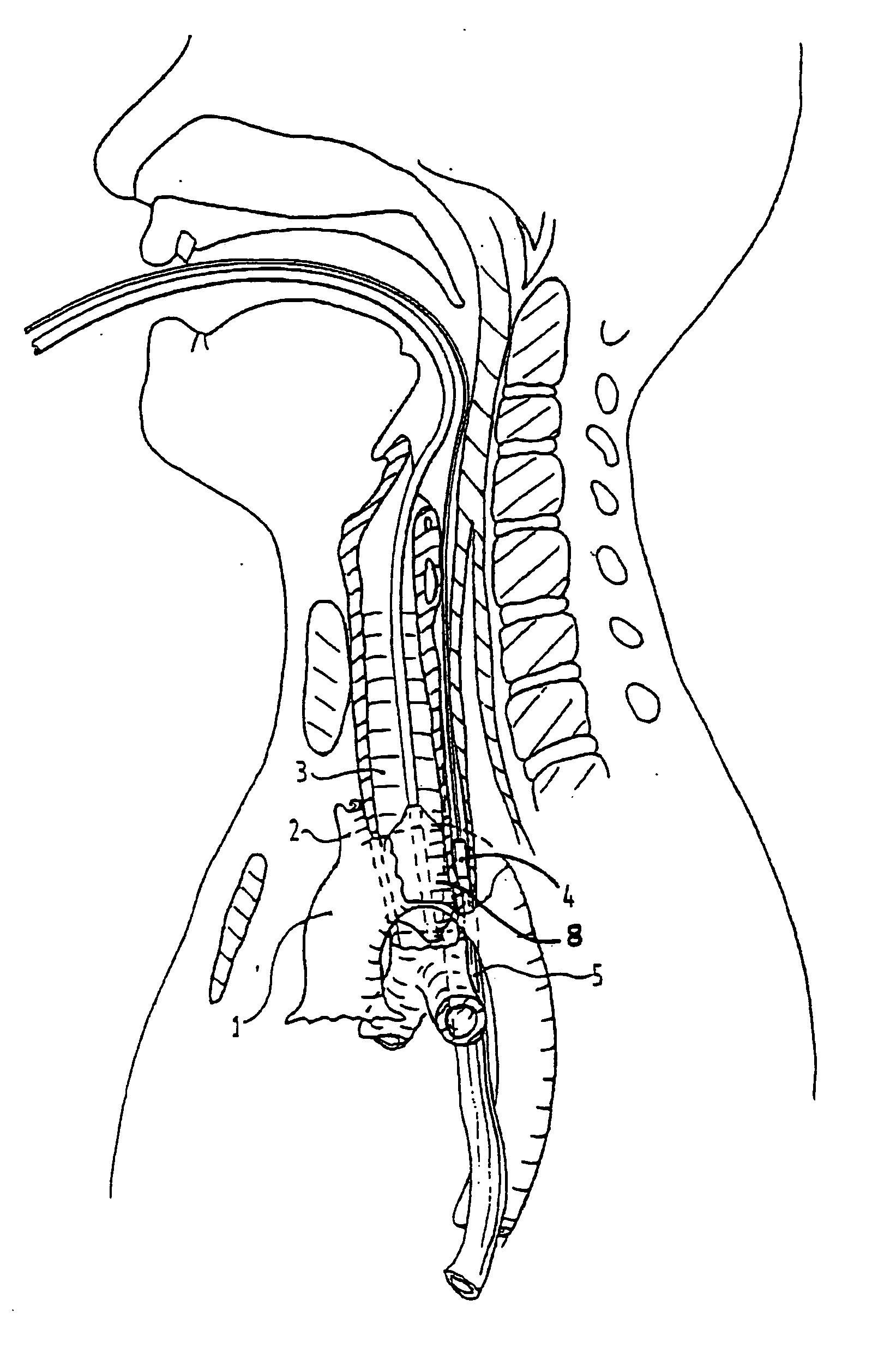
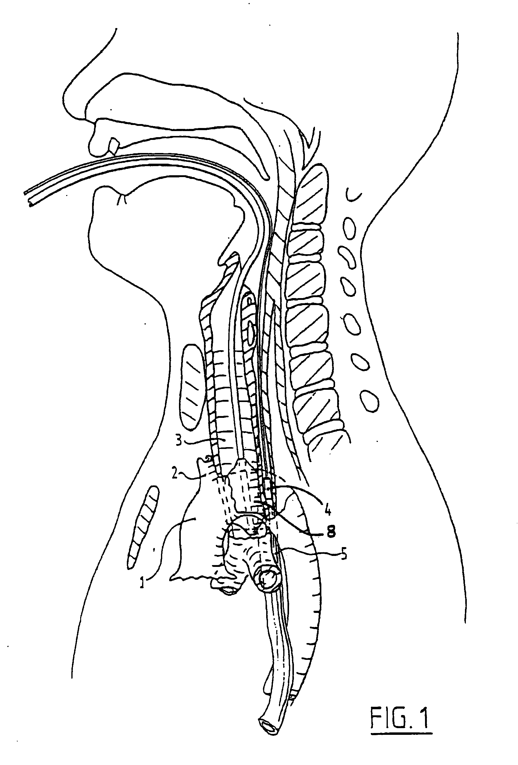
[0048] As explained in the description visualization of the aorta ascendens 1 and the upper part of the main vascular side branches 2 is difficult to view because an obstruction of the trachea 3 disturbs the ultrasound waves originating from an echoprobe 4 in the esophagus 5. When a patient is intubated with a transmission device according to the invention, which normally consists of a distensible balloon connected to a supply line for a sound wave transmission fluid medium, a suitable sound wave path is formed for the sound waves originating from an ultrasound endoscope positioned in the esophagus 5. An optimal visualization of these parts of the aorta is thus obtained by a combined use of an endoscope device and a transmission device forming an ultrasonic imaging system according to the invention.

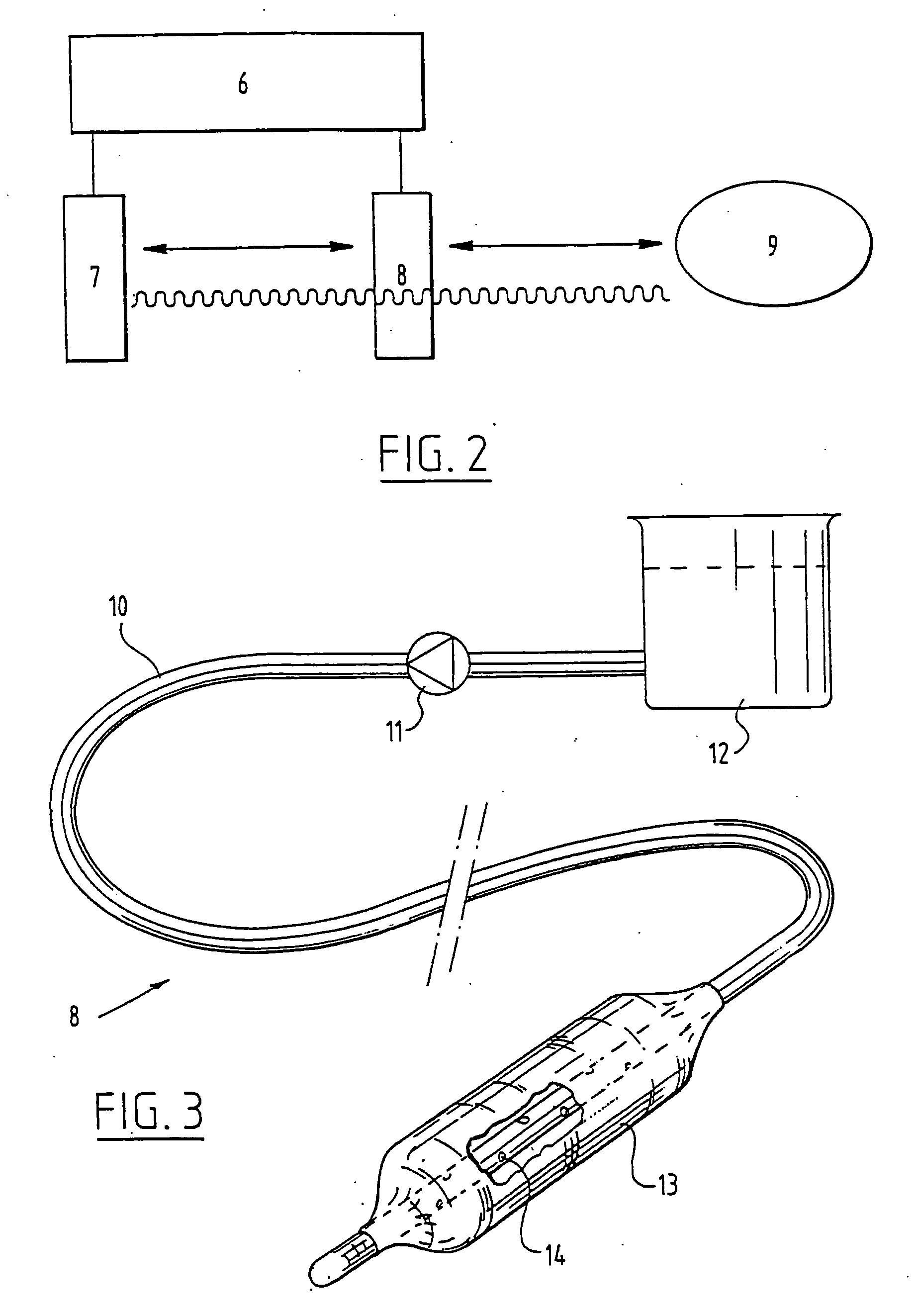
[0049]FIG. 2 shows very schematically an ultrasonic imaging system 6 comprising an ultrasound endoscope 7 and a separate transmission device 8. When viewed with a target organ 9 ultrasou...


PUM


Abstract

The invention relates to an ultrasonic imaging system having an ultrasound intra-esophageal endoscope device for scanning a patient's organs, for use in particular with transesophageal echocardiography, and an intratracheal transmission device defining a transmission path for sound waves originating from the endoscope device. A transmission device is specially adapted for use with an endoscope device in an ultrasonic imaging system having a flexible balloon member connected to a supply line for a sound wave transmission fluid medium.

Description

CROSS REFERENCE TO RELATED APPLICATIONS [0001] This application is a continuation-in-part application of U.S. application Ser. No. 10 / 221,250, filed Sep. 10, 2002, which claims the benefit of priority to PCT Application No. PCT / EP00 / 02212, filed Mar. 10, 2000 and European Application No. 99200703.9, filed Mar. 10, 1999, which are incorporated herein by reference in their entirety.BACKGROUND OF THE INVENTION [0002] 1. Field of the Invention [0003] The invention relates to an ultrasonic imaging system comprising an ultrasound endoscope device for scanning a patient's organs, in particular for use in transesophageal echocardiography. [0004] 2. Description of the Prior Art [0005] Such a device specially adapted for transesophageal echographic scanning is for example disclosed in U.S. Pat. No. 5,105,819. [0006] Transesophageal echocardiography (TEE) has become a widely used imaging technique for evaluating cardiac structure, function, and valvular anatomy. Transesophageal echocardiograph...

Claims


Application Information

Patent Timeline
Patent Type & Authority Applications(United States)
IPC IPC(8): A61B8/14A61B5/03A61B8/00A61B8/12
CPCA61B8/12A61B5/037
Inventor NIERICH, ARNO
Owner STROKE2PREVENT
Why Eureka
Try Eureka