Method of activating carbon monoxide removing catalyst, carbon monoxide removing catalyst, method of removing carbon monoxide and method of operating fuel cell system

a carbon monoxide removal and catalyst technology, applied in the field of carbon monoxide removal, can solve the problems of electrode catalyst poisoning, low activity, and need to add an excessive amount of oxidizer (oxygen) thereto, so as to reduce the initial activity of the carbon monoxide removal catalyst, reduce the loss of hydrogen, and reduce the effect of energy consumption

Inactive Publication Date: 2007-03-01
OSAKA GAS CO LTD
View PDF7 Cites 2 Cited by
  • Summary
  • Abstract
  • Description
  • Claims
  • Application Information

AI Technical Summary

Benefits of technology

[0017] Through extensive research, the present inventors discovered that the carbon monoxide removing catalyst can be significantly activated by being caused to contact an inactive gas or a hydrogen-containing inactive gas consisting of less than 50 volume % of hydrogen gas and the remaining volume of inactive gas and has perfected this invention based on this discovery. When the carbon monoxide remover accommodating therein the carbon monoxide removing catalyst activated in the manner described above is operated at a low temperature (e.g. 70 to 120° C.), a good carbon monoxide removing activity can be obtained from the start of the operation. Incidentally, it has been revealed that if a low ratio of hydrogen is added to the above-described inactive gas, the carbon monoxide removing catalyst after the activation can provide high oxidation performance and also energy consumption can be restricted even when the activating temperature for the carbon monoxide removing catalyst is lowered. In practice, less than 50 volume % is sufficient as the ratio of the hydrogen to be added to the inactive gas.
[0062] Here, if the carbon monoxide removing catalyst is activated with the hydrogen-containing inactive gas at from 80 to 250° C., the concentration of carbon monoxide present in the reformed gas can be reduced to be less than 100 ppm (see FIGS. 3 through 5 and Table 2). Further, if the carbon monoxide concentration is reduced to such level, it is possible to obtain the reformed gas which can be supplied to the solid polymer fuel cell from the beginning of the operation of the carbon monoxide remover. Further, if the activation is effected at a temperature from 120 to 250° C., it is possible to reduce the carbon monoxide concentration to be lower than 10 ppm (see FIGS. 3 through 5 and Table 2). If the carbon monoxide concentration is reduced to such level, this will provide an effect of significantly restricting the poisoning of the electyrode catalyst of the fuel cell with carbon monoxide, thereby to extend the service life of the electrode catalyst.

Problems solved by technology

However, in the case of a fuel reforming apparatus for producing a reformed gas for use in a polymer electrolyte fuel cell, since this polymer electrolyte fuel cell operates at a low temperature of about 80° C., its electrode catalyst will be poisoned even if just a trace amount of carbon monoxide is present.
However, in order to remove carbon monoxide from the above-described reformed gas to achieve its concentration of 10 ppm or less by using the conventional carbon monoxide removing catalyst, it was necessary to add an excessive amount of oxidizer (oxygen) thereto.
), its catalyst activity is low, so that carbon monoxide could not be removed effectively.
Therefore, if the carbon monoxide removing catalyst is used at a high temperature range in order to remove a greater amount of carbon monoxide, there occurs the problem of the above-described methanation reaction being very much promoted.
This is problematic, not only in that the hydrogen needed by the fuel cell is consumed inadvertently in the methanation reaction, but also in that the temperature will be further elevated due to the reaction heat from the methanation reaction.
Moreover, there is still another problem of the carbon monoxide removing catalyst being poisoned with iron, thus resulting in performance degradation.
As this iron carbonyl moves together with the mixture gas to adhere to the catalyst portion of the carbon monoxide remover, this carbon monoxide removing catalyst will be poisoned.

Method used


Image

  • Method of activating carbon monoxide removing catalyst, carbon monoxide removing catalyst, method of removing carbon monoxide and method of operating fuel cell system
  • Method of activating carbon monoxide removing catalyst, carbon monoxide removing catalyst, method of removing carbon monoxide and method of operating fuel cell system
  • Method of activating carbon monoxide removing catalyst, carbon monoxide removing catalyst, method of removing carbon monoxide and method of operating fuel cell system

Examples


example 1

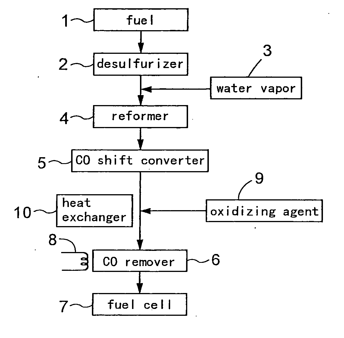
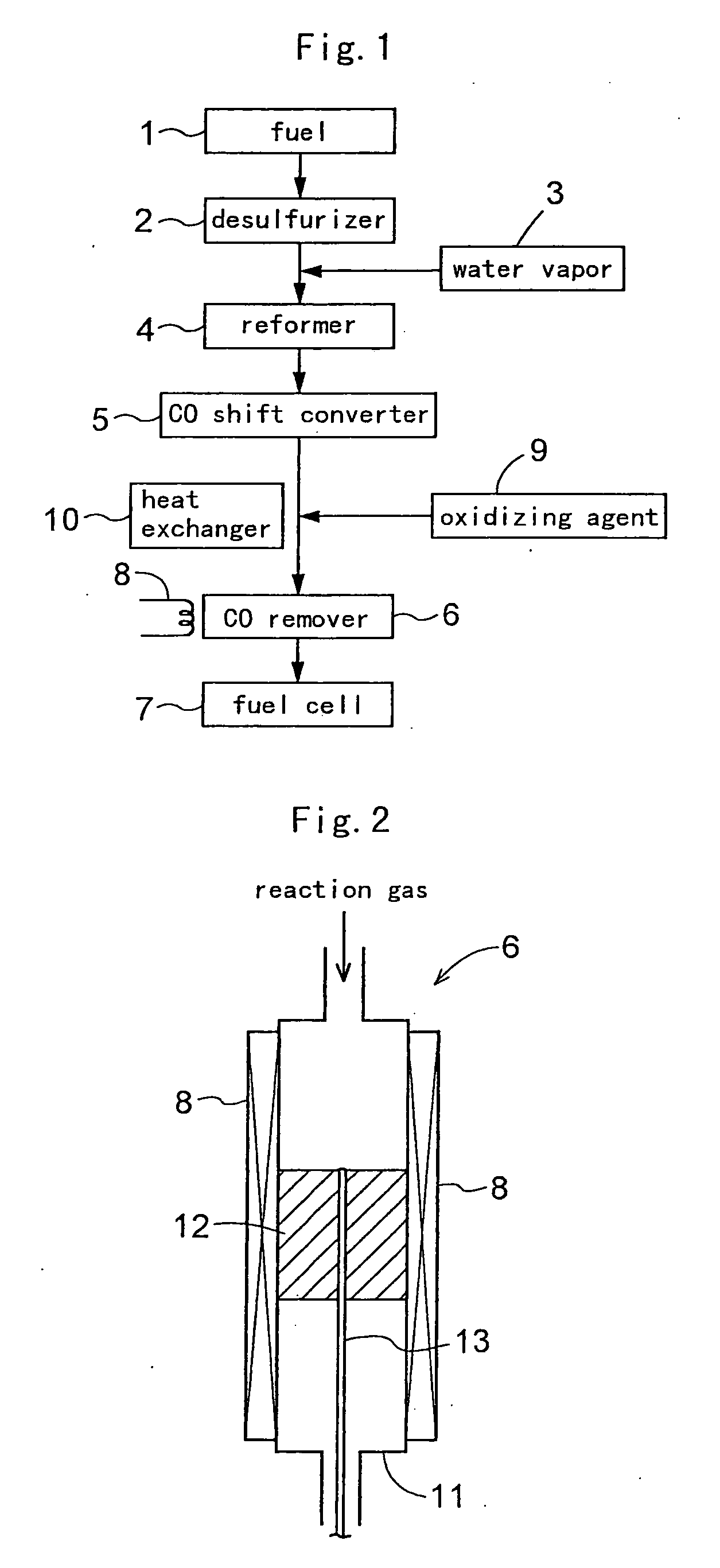
[0093] As described hereinbefore, a carbon monoxide remover 6 was prepared by charging, into a stainless steel reaction tube 11, 8 cc of Ru / alumina catalyst (carbon monoxide removing catalyst) including a support of an alumina sphere of a diameter of 2 to 4 mm and ruthenium (Ru) supported on this support. This carbon monoxide remover 6 include a temperature adjusting means 8 having a heater capable of heating the reaction tube 11 from the outside and a cooler capable of cooling the tube, so that the temperature of the reaction tube 11 is controllable.

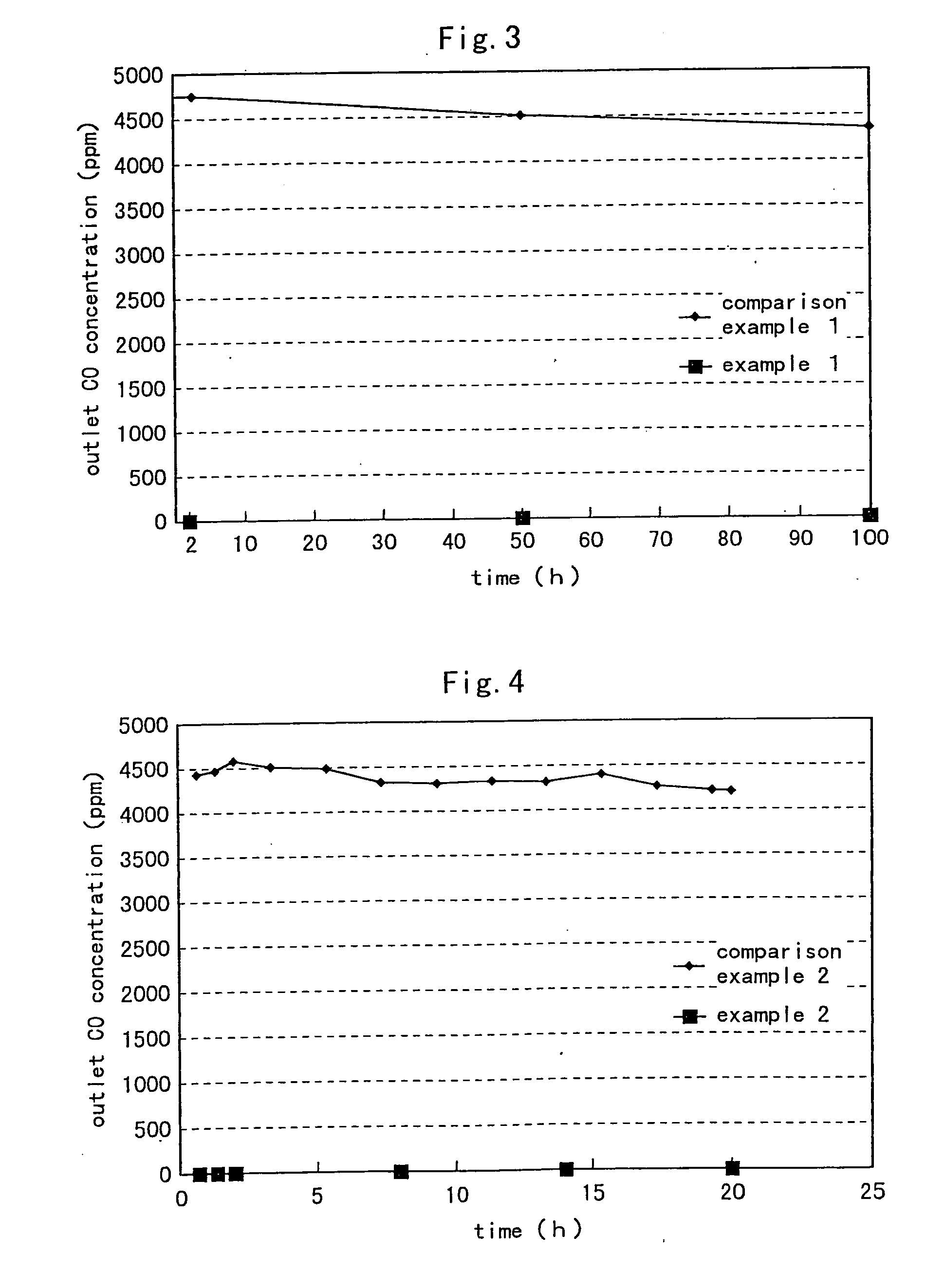
[0094] Then, while introducing the hydrogen-containing inactive gas (hydrogen: 6%, nitrogen: 94%) for activating the carbon monoxide removing catalyst at the flow rate of 1000 cc / min. to this carbon monoxide remover 6 (the ruthenium supporting amount of the carbon monoxide removing catalyst: 1.0 wt. %), the remover was heated by the temperature adjusting means until the reaction tube temperature reached 250° C. and was maintained at 25...

example 2

[0096] While introducing the hydrogen-containing inactive gas (hydrogen: 10 volume %, nitrogen: 90 volume %) for activating the carbon monoxide removing catalyst at the flow rate of 1000 cc / min. to the carbon monoxide remover 6 (1.0 wt. % for the ruthenium supporting amount of the carbon monoxide removing catalyst), the remover was heated by the temperature adjusting means until the reaction tube temperature reached 200° C. and was maintained at 200° C. for 2 hours (pre-treatment).

[0097] After this pre-treatment, the temperature of the reaction tube 11 was lowered to 110° C. and maintained at 110° C., and the simulated reaction gas was introduced into the reaction tube 11 at space velocity (GHSV): 7500 / h, thereby to allow an oxidizing removing reaction for carbon monoxide to take place. Incidentally, the simulated reaction gas employed was a gas having a composition (i.e. carbon monoxide: 0.5%, methane: 0.5%, carbon dioxide: 20.9%, oxygen: 0.8%, nitrogen: 3.1%, water (vapor): 20% a...

example 3

[0098] In this Example 3, by using the carbon monoxide remover 6 (0.5 wt. % for 15 the ruthenium supporting amount of the carbon monoxide removing catalyst), the pre-treatment was effected in the same manner as Example 2, except for setting the oxidation removal temperature for carbon monoxide to 120° C. FIG. 5 shows the exit (outlet) carbon monoxide concentration (determined by the gas chromatograph apparatus) obtained when the oxidation removal was effected in the above-described manner.


PUM

PropertyMeasurementUnit
temperatureaaaaaaaaaa

Abstract

A carbon monoxide removing catalyst such as a ruthenium supporting catalyst is provided for removing, through oxidation thereof, carbon monoxide from an alcohol reformed gas containing hydrogen and carbon monoxide to be supplied to a fuel cell. For its activation, the catalyst is caused to contact an inactive gas or a hydrogen-containing inactive gas consisting of less than 50 volume % of hydrogen gas and the remaining volume of inactive gas, thereby to avoid poisoning of the electrode of the fuel cell with carbon monoxide.

Description

CROSS REFERENCE TO RELATED APPLICATION [0001] This application is a Divisional Application of U.S. patent application Ser. No. 10 / 380,811, filed Mar. 18, 2003, which is the national phase of Japanese Application No. PCT / JP01 / 08023, filed Sep. 14, 2001, which claims priority to Japanese Application No. 2001 140385, filed May 10, 2001, and to Japanese Application No. JP 2000 281936, filed Sep. 18, 2000.BACKGROUND OF THE INVENTION [0002] 1. Field of the Invention [0003] The present invention relates to a carbon-monoxide removing (removal) catalyst for removing mainly carbon monoxide from a gas containing hydrogen (H2) gas as the major component thereof and containing also a small amount of carbon monoxide (CO) gas, such as a reformed gas obtained by reforming (steam reforming, partial oxidation reforming, etc.) a hydrocarbon such as a natural gas, naphtha, kerosene or the like and an alcohol such as methanol. The invention relates also to a method of removing carbon monoxide therefrom ...

Claims


Application Information

Patent Timeline
Patent Type & Authority Applications(United States)
IPC IPC(8): H01M8/06B01D53/62C01B32/40B01J21/04B01J23/46B01J35/00B01J35/08B01J37/02B01J37/16B01J37/18C01B3/58C10K3/04
CPCB01J21/04Y02E60/50B01J35/0006B01J35/002B01J35/08B01J37/0205B01J37/16B01J37/18C01B3/583C01B2203/0227C01B2203/0283C01B2203/044C01B2203/047C01B2203/066C10K3/04H01M8/0612H01M8/0618H01M8/0662H01M8/0668H01M8/0675B01J23/462Y02A50/20
Inventor ECHIGO, MITSUAKITABATA, TAKESHISASAKI, HIROKAZUYAMAZAKI, OSAMU
Owner OSAKA GAS CO LTD
Why Eureka
Try Eureka