Cantilever and inspecting apparatus

a technology of inspection apparatus and cantilever, which is applied in the direction of material analysis using wave/particle radiation, instruments, nuclear engineering, etc., can solve the problems of difficult to lower the current spring load of the cantilever, affecting the accuracy of inspection data provided by the lsi inspection apparatus and lithography apparatus, and causing bends or buckles. , to achieve the effect of improving the stiffness of the probe, improving the accuracy of image data provided by the lsi inspection

Inactive Publication Date: 2007-03-08
HITACHI KENKI FINE TECH CO LTD +1
View PDF2 Cites 28 Cited by
  • Summary
  • Abstract
  • Description
  • Claims
  • Application Information

AI Technical Summary

Benefits of technology

[0031] According to the inventive cantilever with a carbon nanotube and the inventive method of manufacturing the cantilever, the stiffness of the probe is increased, so the probe is hard to warp when the probe is pushed against a sample. Accordingly, the precision of image data provided by the LSI inspecting apparatus and lithography apparatus can be increased. This addresses problems caused during measurement by use of an AFM in which a cantilever with a carbon nanotube is used, due to a bend or buckle of the carbon nanotube; the problems are, for example, that an image that represents a shape different from the intrinsic surface shape of the sample is obtained as a result of measurement, the joining portion of the carbon nanotube is destructed by charges, and image failures occurs. Therefore, stable AFM-based measurement can be performed.
[0032] Accordingly, an atomic force microscope that enables highly precious measurement with a high resolution can be achieved by taking advantage of the fact that the carbon nanotube described above is thin.
[0033] In addition, since the life of the cantilever can be prolonged, highly precious, stable measurement with a high resolution can be practiced for a long period of time. This enables manufacturing of products, such as LSI chips, that need highly precious shape measurement (inspection process) in the course of manufacturing.

Problems solved by technology

If a carbon nanotube is used as the probe in these operation modes, a buckle and bend of the carbon nanotube cause a problem.
If an excessive approach load is set for the carbon nanotube probe in the modes described above, a bend or buckle is caused when the carbon nanotube comes into contact with the sample.
Accordingly, an image obtained as a measurement result, which should represent the state of the sample surface, represents a shape different from the intrinsic surface shape; the carbon nanotube probe is released from the cantilever, disabling measurement from being continued, and other problems occur.
When the strength of the entire cantilever and its material are considered, it is difficult to lower the current spring load of the cantilever.

Method used


Image

  • Cantilever and inspecting apparatus
  • Cantilever and inspecting apparatus
  • Cantilever and inspecting apparatus

Examples


first embodiment

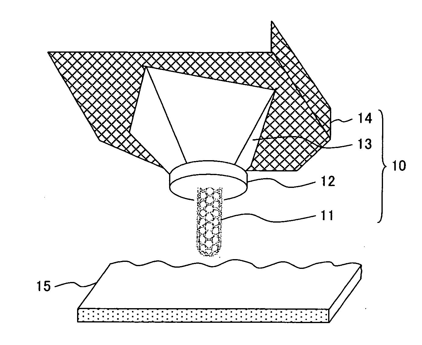
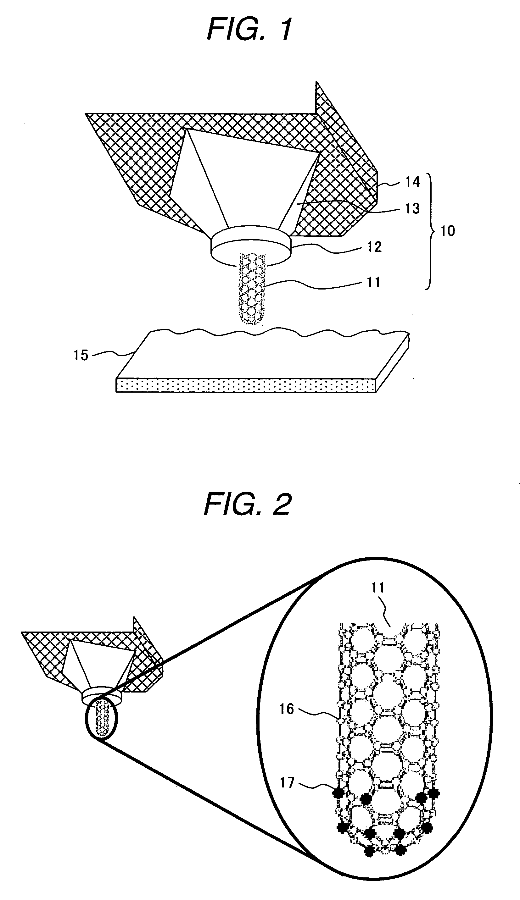
[0075] In a first embodiment of the present invention shown in FIGS. 5 to 7, a single carbon nanotube probe 11 is fixed at an end of a holder 13 with a metal layer. FIG. 5 is a perspective view of the probe of the inventive cantilever. FIG. 6 generally shows the cantilever including the cantilever probe shown in FIG. 5. As shown in FIG. 6, the cantilever has a chip, which comprises a carbon nanotube probe 11, end joint layer 12-1, middle joint layer 12-2, root joint layer 12-3, and holder 13, and also includes a base 18; the chip is provided at one end (free end) of the beam 14 and the base 18 is disposed at the other end (fixed end). The middle joint layer 12-2 and root joint layer 12-3, which are metal layers, are used as fixing layers for fixing the probe 11 to the holder 13.

[0076]FIG. 7 is a cross-sectional view of the probe shown in FIG. 5. As shown in FIG. 7, the end joint layer 12-1 is separated into a supporting joint layer 12-1-1 on the obtuse angle side and a pressing joi...

second embodiment

[0097] An embodiment of an LSI inspecting apparatus having the inventive cantilever that uses a carbon nanotube including heteroatoms will be described with reference to FIG. 10. The LSI inspecting apparatus in this embodiment has a cantilever 10, which comprises a probe 11 formed by use of a hetero carbon nanotube and a beam 14 that supports the probe 11, and a contact detector for detecting that the cantilever 10 touches an LSI chip under test on a sample base 15. The contact detector comprises a laser source 51, a laser reflecting mirror 52, a light detector 53, and an amplifier 54 for amplifying an optical signal detected by the light detector 53. The apparatus further includes a Z-axis servo circuit 55 for feeding back a signal from the amplifier 54, a piezoelectric device 61 for adjusting the position of the sample base 15 in the height direction by use of a signal from the Z-axis servo circuit 55, an XY scanning circuit 56 necessary for obtaining two-dimensional surface infor...

third embodiment

[0099] An embodiment of a lithography apparatus having the inventive cantilever will be described with reference to FIG. 11. The lithography apparatus in this embodiment has substantially the same structure as the LSI inspecting apparatus shown in FIG. 10, except that a lithography power supply 90 for electrically connecting the cantilever 10 to the sample base 15 is provided. The hetero cantilever 10 is characterized in that it is hydrophilic. The use of the property enables the cantilever 10 to be employed as the probe 11 of the lithography apparatus. When the probe 11 of the cantilever 10 is brought into contact with a sample 45 under test by the lithography apparatus, a part brought into contact is covered with absorbed water 49. When current is passed through the absorbed water 49, the sample 45 is anodized, making lithographing possible.


PUM


Abstract

The present invention provides a cantilever having a base fixed to an inspecting apparatus, a beam protruding from the base, and a probe fixed to an end of the beam, wherein: the probe is formed by use of a carbon nanotube; and the probe is fixed by metal layers from at least two directions when the cantilever is operated, the probe protrudes in a direction in which a sample is fixed. It is possible to prevent the probe from warping and suppress image failures during observation of a sample.

Description

CLAIM OF PRIORITY [0001] The present application claims priority from Japanese application serial No. 2005-251767, filed on Aug. 31, 2005 and Japanese application serial No. 2006-080267, filed on Mar. 23, 2006, the contents of which are hereby incorporated by references into this application. BACKGROUND OF THE INVENTION [0002] 1. Field of Technology [0003] The present invention relates to a cantilever that uses a carbon nanotube as a probe and to a method of manufacturing the cantilever. The invention also applies to an LSI inspecting apparatus and a lithography apparatus that uses the inventive cantilever. [0004] 2. Background of Art [0005] An atomic force microscope (AFM) is a type of scanning probe microscope (SPM). An exemplary AFM is an apparatus in which a cantilever having a sharp probe is mounted and the cantilever probe is brought into contact with a sample to scan the sample, thereby measuring a surface of the sample. A feedback mechanism that raises and lowers the cantile...

Claims


Application Information

Patent Timeline
Patent Type & Authority Applications(United States)
IPC IPC(8): G21K7/00G01Q10/00G01Q60/24G01Q60/38G01Q70/12
CPCB82Y15/00G01Q70/12G01Q60/38B82Y35/00G01Q70/02
Inventor HIDAKA, KISHIOHIROOKA, MOTOYUKIHAYASHIBARA, MITSUOFUJIEDA, TADASHITANAKA, HIROKITAKESHI, NORIAKIMORIMOTO, TAKAFUMISEKINO, SATOSHITAKASHINA, MASATOUOZUMI, YUKI
Owner HITACHI KENKI FINE TECH CO LTD
Why Eureka
Try Eureka