
Polymer Electrolyte Battery and Method for Manufacturing Same

a technology of polymer electrolyte and electrolyte, which is applied in the direction of wound/folded electrode electrodes, non-aqueous electrolyte cells, non-metal conductors, etc., can solve the problems of inconvenient generation, inability to efficiently use the inner space of the electronic device b>101/b>, and inability to use the space efficiently, etc., to achieve good battery characteristics

Inactive Publication Date: 2007-03-15
MURATA MFG CO LTD
View PDF7 Cites 39 Cited by
  • Summary
  • Abstract
  • Description
  • Claims
  • Application Information

AI Technical Summary

Benefits of technology

The coiled battery element maintains excellent battery characteristics and reduces the likelihood of short-circuits at the electrode ends, enabling efficient space utilization in curved electronic device compartments while maintaining performance over time.

Problems solved by technology

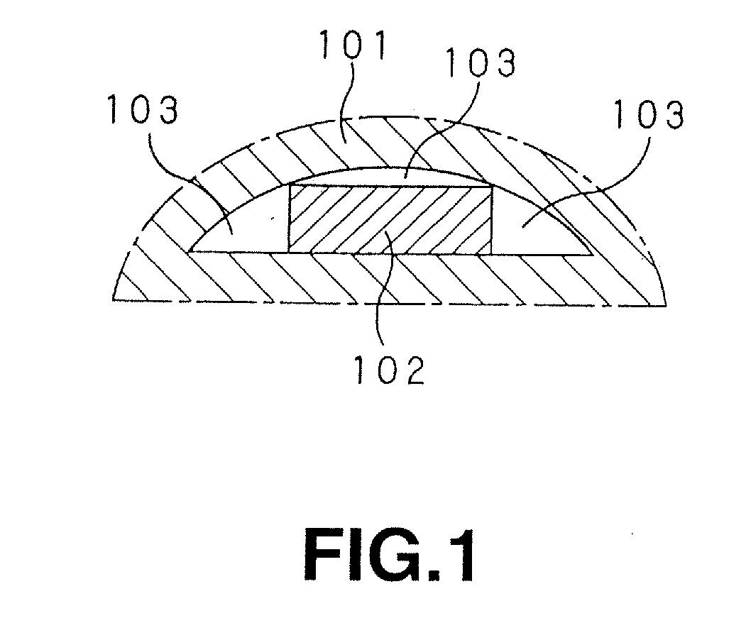
However, for instance, as shown in FIG. 1, when a flat plate type polymer electrolyte battery 102 is attached to an inner space having a curved surface in a portable electronic device 101 such as a portable telephone or a PDA, useless spaces 103 are inconveniently generated between the casing of the electronic device 101 and the flat plate type polymer electrolyte battery 102 so that the inner space of the electronic device 101 cannot be efficiently used.
However, since the flat plate type polymer electrolyte battery 102 has a flat plate type battery element including a thin sheet type cathode and a thin sheet type anode and a polymer electrolyte interposed therebetween, even when the flat plate type polymer electrolyte battery 102 is curved, a desired curved form cannot be held for a long time.
Further, an electrode active material layer may be cracked or further may be separated from a current collector due to an external force when the flat plate type battery element is bent.
Therefore, when the flat plate type polymer electrolyte battery 102 is bent, battery characteristics are disadvantageously extremely deteriorated.
According to this method, although the curved configuration of the battery element is maintained, a shearing stress by the rolls with different diameter is exerted on a part between an active material layer and a current collector, so that the resistance of a cell is undesirably increased, a short-circuit is apt to be generated at the end of a stacked electrode, and accordingly, a stable battery performance cannot be inconveniently obtained.
Further, not only the curvature of a desired curved configuration can be extremely hardly obtained, but also the thickness of a cell is inconveniently greatly regulated.

Method used


Image

  • Polymer Electrolyte Battery and Method for Manufacturing Same
  • Polymer Electrolyte Battery and Method for Manufacturing Same
  • Polymer Electrolyte Battery and Method for Manufacturing Same

Examples


example 1

[Manufacture of Cathode]

[0105] As components of a cathode composite mixture, LiCoO2 of 92 parts by weight as a cathode active material, powdered graphite of 5 parts by weight as a conductive material and powdered polyvinylidene fluoride of 3 parts by weight as a binding agent were measured and used. Then, these components were dispersed in N-methyl pyrrolidone to prepare the slurry of the cathode composite mixture.

[0106] The cathode composite mixture thus prepared was uniformly applied to both the surfaces of a cathode current collector made of an aluminum foil (having the thickness of 20 m), and then dried under reduced pressure at the temperature of 100° C. for 24 hours so that cathode active material layers were formed. Then, the cathode active material layers were compression-molded by using a roll press machine to form a cathode sheet. After that, the cathode sheet was cut to manufacture a band shape cathode having length of 50 mm and width of 300 mm. As a cathode lead, an al...

example 2

[0114] A polymer electrolyte battery was manufactured in the same manner as that of the Example 1 except that a flat type battery element sealed in outer package films was subjected to a thermocompression bonding process by using a heat press machine including a recessed heater block and a flat surface type heater block so that the section of the battery element perpendicular to a coiling axis had a substantially semicircular form.

example 3

[0115] A polymer electrolyte battery was manufactured in the same manner as that of the Example 1 except that a flat type battery element sealed in outer package films was subjected to a thermocompression bonding process by using a heat press machine including a recessed heater block having a flat surface part in the central part of a curved surface part and a silicon rubber sheet with the thickness of 1 mm stuck thereto and a protruding heater block having a flat surface part in the central part of a curved surface part so that the section of the battery element perpendicular to a coiling axis had a curved form having a flat part at least in a part thereof.


PUM

PropertyMeasurementUnit
thicknessaaaaaaaaaa
temperatureaaaaaaaaaa
widthaaaaaaaaaa

Abstract

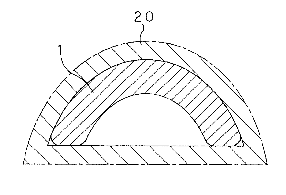
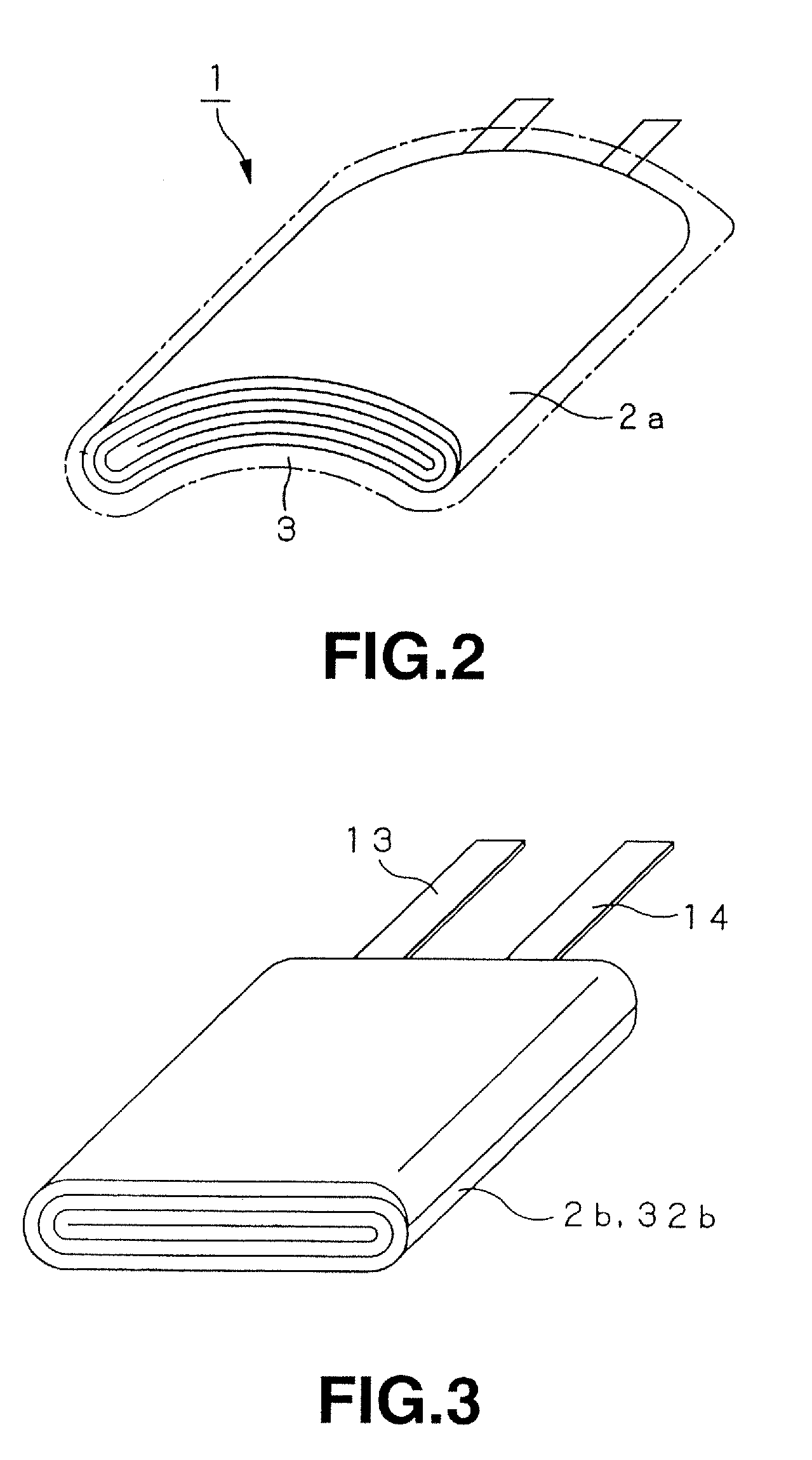
In a polymer electrolyte battery including a battery element having a cathode and an anode coiled through a polymer electrolyte, a section of the battery element perpendicular to the coiling axis has a curved form. As compared with a polymer electrolyte battery having a flat plate type battery element curved, the former battery has an extremely low possibility of short-circuit at the end of an electrode and excellent battery characteristics.

Description

TECHNICAL FIELD [0001] The present invention relates to a polymer electrolyte battery having a battery element in which a cathode and an anode are coiled through a polymer electrolyte and a method for manufacturing it, and more particularly to an improvement of the form of the battery element. BACKGROUND ART [0002] In recent years, as portable electronic devices are made compact and the weight of them are reduced, it has been highly demanded for batteries which supply electric power to these electronic devices to decrease their size, thickness or weight irrespective of uses thereof such as driving means or backup means. [0003] As a battery for satisfying such a demand, has been developed and put into practical use a nonaqueous electrolyte battery, what is called a lithium battery which includes a cathode and an anode having active materials capable of reversibly inserting and extracting lithium ions and a nonaqueous electrolyte and has such advantages as a high output and high energ...

Claims


Application Information

Patent Timeline
Patent Type & Authority Applications(United States)
IPC IPC(8): H01M2/02H01M10/04H01M10/05H01B1/12H01M4/62H01M4/66H01M6/06H01M6/10H01M6/18H01M10/0565H01M10/0587H01M50/119H01M50/121H01M50/129
CPCH01B1/122Y10T29/49114H01M2/0287H01M4/485H01M4/525H01M4/583H01M4/622H01M4/66H01M6/10H01M10/04H01M10/0431H01M10/0525H01M10/0565H01M2002/0205H01M2004/025H01M2006/106H01M2010/0495H01M2300/0082H01M2300/0085H01M2/0275Y02E60/10H01M50/124Y02P70/50H01M10/058H01M50/121H01M50/129H01M50/119
Inventor ENDO, TAKAHIROKEZUKA, KOICHIROHATTA, KAZUHITOKONDO, TAKAYUKI
Owner MURATA MFG CO LTD
Learn More