Multiple wireless sensors for dialysis application

a wireless sensor and dialysis technology, applied in the field of sensing devices and methods, can solve the problems of inability to use mechanical fluid removal in the icu, emergency rooms and general floors of the hospital, and inability to achieve smooth blood path, so as to maximize the amplitude of spurs for detection.

Inactive Publication Date: 2007-03-15
HONEYWELL INT INC
View PDF19 Cites 17 Cited by
  • Summary
  • Abstract
  • Description
  • Claims
  • Application Information

AI Technical Summary

Benefits of technology

[0023] An alternative embodiment involves the use of wireless LC tank multiple sensors in the context of a sensor system in which the sensors share a single antenna. Multiple capacitors, each of which forms a variable C component in the LC tank sensor, can be linked with

Problems solved by technology

This allowed flexibility, but also resulted in certain disadvantages.
In an acute setting, however, such an Intensive Care Unit (ICU) of a hospital, the complexities of dialysis machines can become an impediment.
As a result, the use of mechanical fluid removal in the ICU, emergency rooms and general floors of a hospital has been limited.
While such devices do offer significant advantages, such equipment also has a number of deficiencies.
One deficiency is that although such systems provide for a set of disposable dialysis components that are continuous and bonded together, the system does not present a smooth blood path, but incorporates elements that create stagnant and slow moving blood zones.
In such blood zones clots are likely to form.
Such devices may also employ an interface to pressure sensors that is relatively inaccurate, unreliable and requires maintenance.
Additional

Method used


Image

  • Multiple wireless sensors for dialysis application
  • Multiple wireless sensors for dialysis application
  • Multiple wireless sensors for dialysis application

Examples


first embodiment

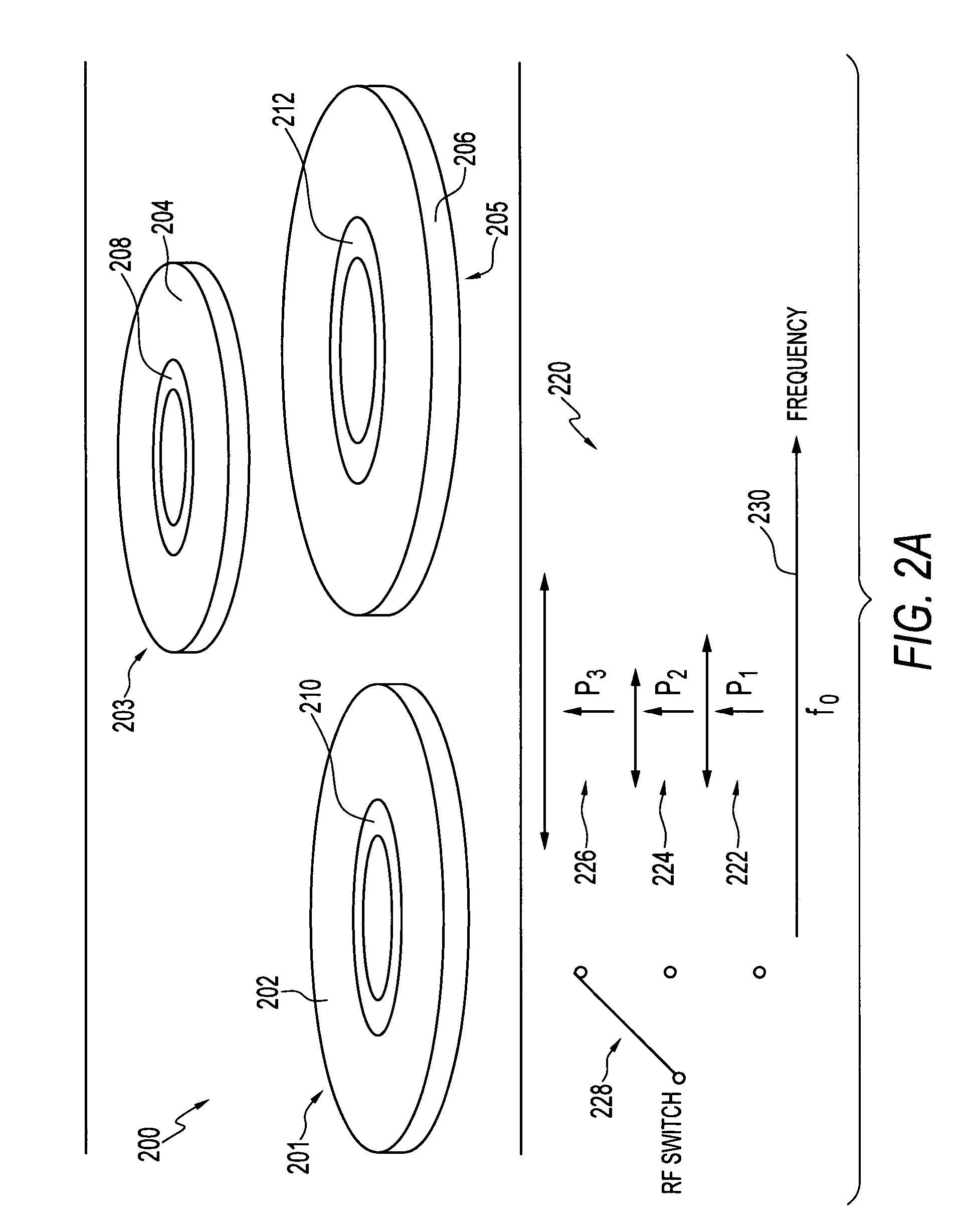
[0040]FIG. 2(b) illustrates a graph 231 depicting how a system of sensors (e.g., see sensors 402, 404, 406 in FIGS. 5-6 and sensors 330, 344 in FIG. 3) can operate in different resonant frequency bands, in accordance with an alternative version of the Note that in FIGS. 2(a)-2(b) identical or similar elements or components are generally indicated by identical reference numerals. Thus, zero pressure frequencies, f0, f02, and f03 are shown along the x-ordinate frequency range 230 in FIG. 2(b).

[0041]FIG. 2(b) indicates that multiple LC tank sensors can operate in different resonant frequency bands to avoid interference between different sensor and antenna signals. Single or multiple interrogation electronics, such as, for example, Grid Dip Oscillator (GDO) circuits, can be utilized depending on the available dynamic range of the GDO circuit. In other words, GDO circuits can be utilized if the frequency range over which the oscillator circuit operates can sustain oscillations. In eithe...

second embodiment

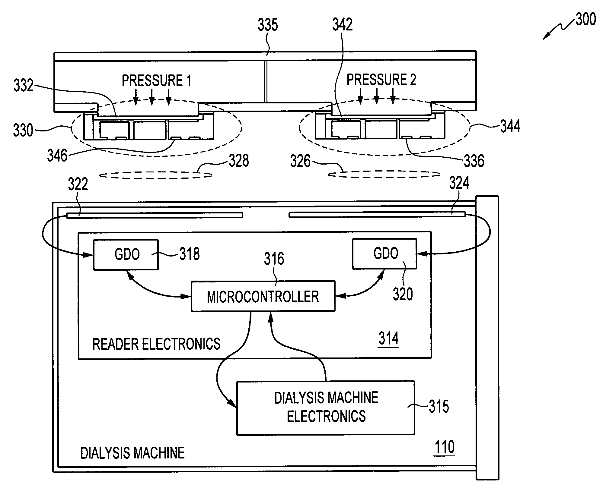
[0059] In general, size limitations for sensors utilized in hemodialysis applications are problematic. It would be beneficial to design a multiple-sensor system with the lowest cost, small size and fewest parts. FIGS. 1-6 represent one possible embodiment. A second embodiment involves the use of wireless LC tank multiple sensors in the context of a sensor system in which the sensors share a single antenna. Multiple capacitors can be linked with a single planar coil, such that each associated variable capacitor results in a signature frequency (i.e., spurs). Multiple characteristic resonant frequencies can be detected in such a system through prudent design.

[0060]FIG. 7 illustrates a graph 700 depicting a variety of frequencies in the context of a sensor system for dialysis applications, in accordance with a second embodiment. In graph 700, f0 represents the fundamental frequency of the sensor system that will not be detected, while f1, f2, and f3 are spurs related to each sensor in,...


PUM


Abstract

A sensor system for dialysis applications includes a plurality of pressure sensors, wherein each pressure sensor can be provided as an LC type sensor, and/or an RLC type sensor. Each sensor among the plurality of pressure sensors can be inductively coupled with a respective antenna among a plurality of antennas for the wireless transmission of pressure data. A dialysis machine is generally connected to the plurality of antennas, wherein the plurality of pressure sensors monitors pressure during operation of the dialysis machine to generate pressure data that is wirelessly transmitted to at least one antenna among the plurality of antennas.

Description

CROSS-REFERENCE TO RELATED PATENT APPLICATIONS [0001] This patent application is a Continuation-In-Part (CIP) of U.S. patent application Ser. No. 11 / 242,271, entitled “Wireless Pressure Sensor and Method Forming the Same,” which was filed on Oct. 3, 2005, and is incorporated herein by reference in its entirety. This patent application is also a Continuation-In-Part (CIP) of U.S. patent application Ser. No. 11 / 226,085, entitled “Wireless Capacitance Pressure Sensor,” which was filed on Sep. 13, 2005, and is incorporated herein by reference in its entirety.TECHNICAL FIELD [0002] Embodiments are generally related to sensing devices and methods. Embodiments are also related to wireless sensors. Embodiments are additionally related to dialysis applications and pressure sensors for use in monitoring pressure during a dialysis application. BACKGROUND OF THE INVENTION [0003] Sensors are utilized in a number of applications, including various medical, commercial and industrial applications. ...

Claims


Application Information

Patent Timeline
IPC IPC(8): G06F19/00
CPCA61M1/3639A61M2205/3592A61M2205/3569A61M1/14A61M1/36224
Inventor LIU, JAMES ZTRAMAMURTHY, GAUTHAMBRADLEY, ALISTAIR D.COOK, JAMES D.SHIFFER, STEPHEN R.
Owner HONEYWELL INT INC
Why Eureka
Try Eureka