This helps you quickly interpret patents by identifying the three key elements:
Problems solved by technology
Method used
Benefits of technology
Benefits of technology
[0068] The present invention is able to keep high calculation accuracy by the addition of these two steps. (2) The second technique in the present invention is one that is based on the first technique, and relates to speedup of computation when the multigrid method is applied to an isolated system in the grid systems of different levels. In this technique, an isolated molecular system is put into every periodic box or periodically iterating unit and the boxes are arranged in a spatially periodic manner, so as to enable application of periodic boundary conditions. FIG. 5 illustrates this technique in one-dimensional system, wherein a circle represents an atom with charge or a grid point with charge. In this scheme, extra buffer areas are inserted between minimum periodic boxes that each contain an isolated molecular system so that the grid points existing in one periodic box are made apart by the kernel's influential outreach distance (i.e., shield distance) or greater from those existing in other periodic boxes. In this way, introduction of periodicity enables use of calculation using the 3D-FFT technique. No particle exists in the added buffer areas. Here, the lengths of the sides of the buffer area are determined based on the influential outreach distance and the grid size.
[0069] In order to clarify the advantages of the second technique, this method will be compared to a case with a single level. In the single level, in order to separate the periodic boxes, it is necessary to set the length of the side of the buffer area to be equal to or greater than the length of the size of the minimum box that contains an isolated system. Therefore, this method needs about twice the number of grid points compared to the multigrid method, so needs longer calculation time with a greater memory capacity. In contrast, in the case of the multigrid method, for fine grid levels the shielding radius is small hence the buffer area is also small, so that it is possible to suppress increase of the number of grid points and increase of the calculation time while for coarse grid levels, the number of grid points itself is low though large buffer areas are needed, resultantly the calculation time can be made short.
[0078] On the other hand, when a lower number of CPUs, specifically about 32 or less CPUs are used, it is impossible to speed. up the computation for an isolated system in the conventional method, in consideration of the performance of PC clusters as of present. In contrast, development of the present invention enables use of 3D FFT method, hence it is possible to enhance the calculation speed while keeping the allowable precision level, compared to the conventional methods.
[0079] Further, in accordance with the present invention, when a dedicated MD board is used in combination, it is possible to achieve fast computation with high precision. In the existing methods, namely the PME method and FMM, particle-particle interactions are calculated for short-range simulation while particle-mesh interactions are calculated for long-range simulation. On the other hand, the dedicated MD boards currently available are ones that perform high speed computation of particle-particle interactions only. It is difficult to develop a MD board for calculating particle-mesh interactions because such interaction is too much complicated. As a result, up to the present, however fast could particle-particle interactions be processed by a dedicated board, there would remain particle-mesh interaction part which should be handled by a general-purpose computer. Hence, there was a limit to raise the total system performance. Since, when using the present invention, the interaction through the short-range kernel between grid points is given based on the same formalism as the Coulomb interaction between particles, a currently available dedicate board can be used to perform calculation of the interactions via the short-range kernel, thus making it possible to drastically reduce the load on the general-purpose machine. Accordingly, the present invention makes it possible to achieve fast computation while keeping high enough accuracy for practical use.
Problems solved by technology
(1) As already described, it has been, impossible for the method of Skeel et al.
This is why error occurs in proportion to about the square of the grid width, causing poor approximation.
Method used
Image
Click on the blue label to locate the original text in one second.
Reading with bidirectional positioning of images and text.
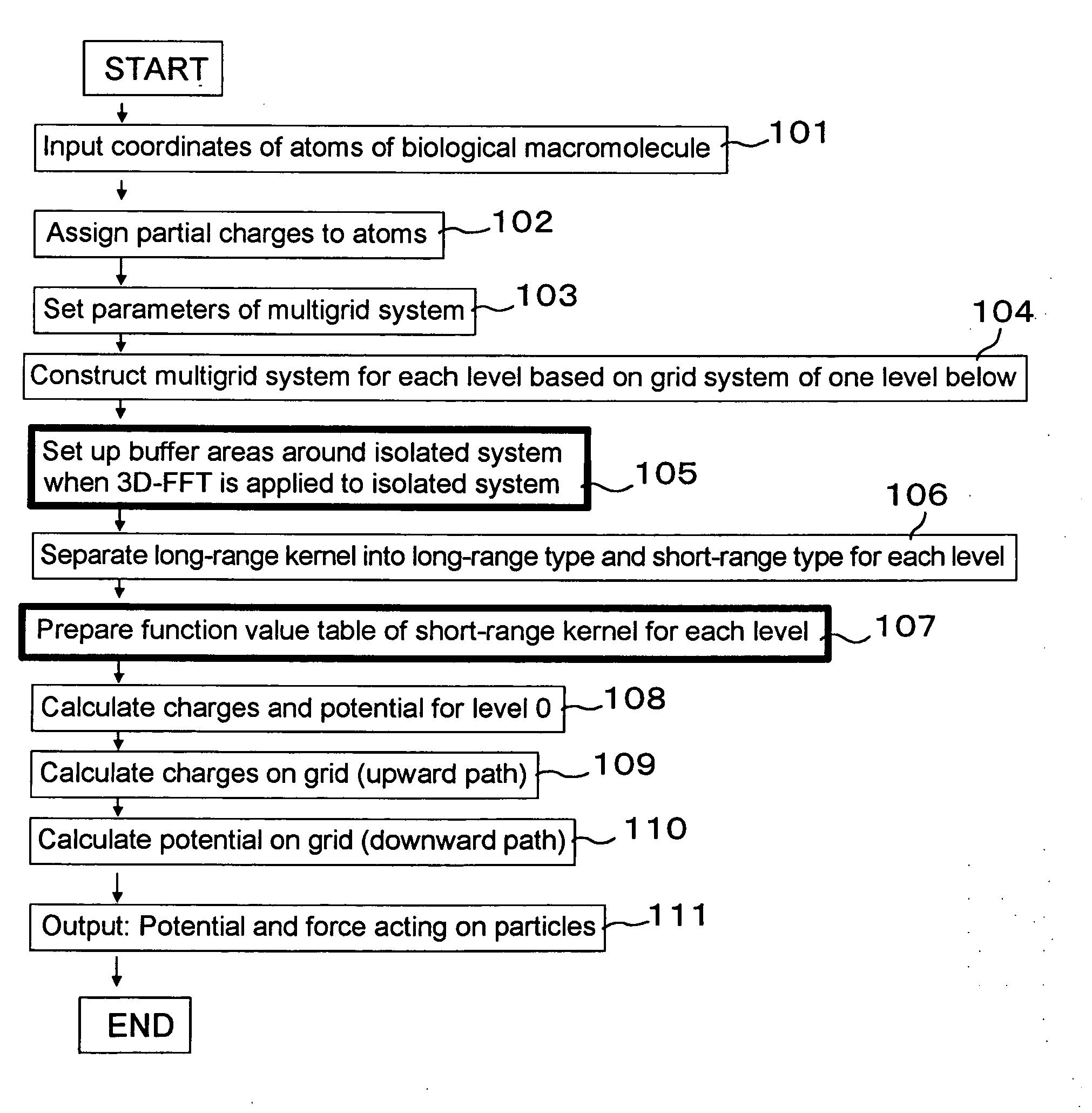
[0097] To begin with, as the first embodiment of the present invention, description will be made on an example in which the molecular simulation method according to the present invention is applied to an isolated system. FIG. 6 shows the total flow of the process in the first embodiment. Here, description will be made on a case where the method of the present invention is applied to molecular simulation of biological macromolecules such as proteins.
[0098] Procedural Steps for Constructing a Multigrid System:
[0099] First, at Step 101, coordinates of atoms of a biological macromolecule are input. Specifically, data depicting the coordinates of every atom that constitutes a target biological macromolecule and the type of the atom is input. For example, data in the PDB (ProteinData Bank) format may be input.
[0100] Next, at Step 102, a molecular computation program (MD code) such as Amber, Charmm or the like is applied to the atomic sys...
[0188] Next, the second embodiment of the present invention will be described. Herein, description will be made on a calculation method suitable for the execution with a dedicated MD board by calculating interactions between grids of the same level, without using FFT while using a periodic boundary condition.
[0189] Similarly to the case of the first embodiment, coordinates of atoms of a molecule to be studied are input and partial charge is added to each atom, and the parameters in the multigrid system are set. Then, a multigrid system is constructed.
[0190] Structuring Method of a Multigrid System for a Periodic System:
[0191] In a case of a periodic system to be handled in the present embodiment, there is no need to add any extra grid. That is, it is not necessary to introduce any buffer area. However, when the maximum value of the used grid levels is represented by Lmax, it is necessary to hold the relation, (the number of grid poin...
PUM
Property
Measurement
Unit
Size
aaaaa
aaaaa
Energy
aaaaa
aaaaa
Interaction
aaaaa
aaaaa
Abstract
In molecular simulation including the step of calculating non-bonding interactions in a system having particles with electric charges, using a multigrid method, upon determining the electric charges at grid points in a coarser grid of a higher level that is one step higher than the level to be observed, when a pair of grid points in the observed level, or a pair of particles in the observed level, both coincide with the grid points of the grid of the higher level, the charges at the grid points of the higher level are determined so that the energy of the pair in the higher level becomes equal to the correct energy value in the observed level.
Description
BACKGROUND OF THE INVENTION [0001] 1. First of the Invention [0002] The present invention relates to a method and apparatus for carrying out molecular simulation based on molecular dynamicssimulation or a molecular Monte Carlo method, and in particular relates to improvement of a multigrid method used for high-speed computation of nonbinding interactions. [0003] 2. Description of the Related Art [0004] General Techniques in Molecular DynamicsSimulation: [0005] Molecular dynamics (MD) simulation of biomolecules is also called molecular simulation, and it is one of the important methodologies that are used for molecular design of remedies against diseases, useful enzymes and the like. The model that is used in the molecular simulation is a so-called molecular mechanics (MM) model. [0006] Describing this molecular mechanics model briefly, molecules to be handled, such as proteins, and water molecules are modeled by beads (particles) connected with springs while the beads, meaning ato...
Claims
Application Information
Patent Timeline
Application Date:The date an application was filed.
Publication Date:The date a patent or application was officially published.
First Publication Date:The earliest publication date of a patent with the same application number.
Issue Date:Publication date of the patent grant document.
PCT Entry Date:The Entry date of PCT National Phase.
Estimated Expiry Date:The statutory expiry date of a patent right according to the Patent Law, and it is the longest term of protection that the patent right can achieve without the termination of the patent right due to other reasons(Term extension factor has been taken into account ).
Invalid Date:Actual expiry date is based on effective date or publication date of legal transaction data of invalid patent.

