
Complete power management system implemented in a single surface mount package

a power management system and surface mount technology, applied in the direction of electric variable regulation, process and machine control, instruments, etc., can solve the problems of more power loss and the inability of the power management system to handle much more current, and achieve the effect of reducing parasitic effects, reducing parasitic effects, and increasing efficiency

Active Publication Date: 2007-03-22
VISHAY SILICONIX LLC
View PDF38 Cites 3 Cited by
  • Summary
  • Abstract
  • Description
  • Claims
  • Application Information

AI Technical Summary

Benefits of technology

[0022] The advantages of using the surface mount packaging include higher current rating, reduced parasitic effects and higher efficiency. In addition, the embodiments of the present invention offer higher power dissipation, lower thermal resistance and a smaller footprint on a next level assembly. Embodiments also offer lower assembly cost.
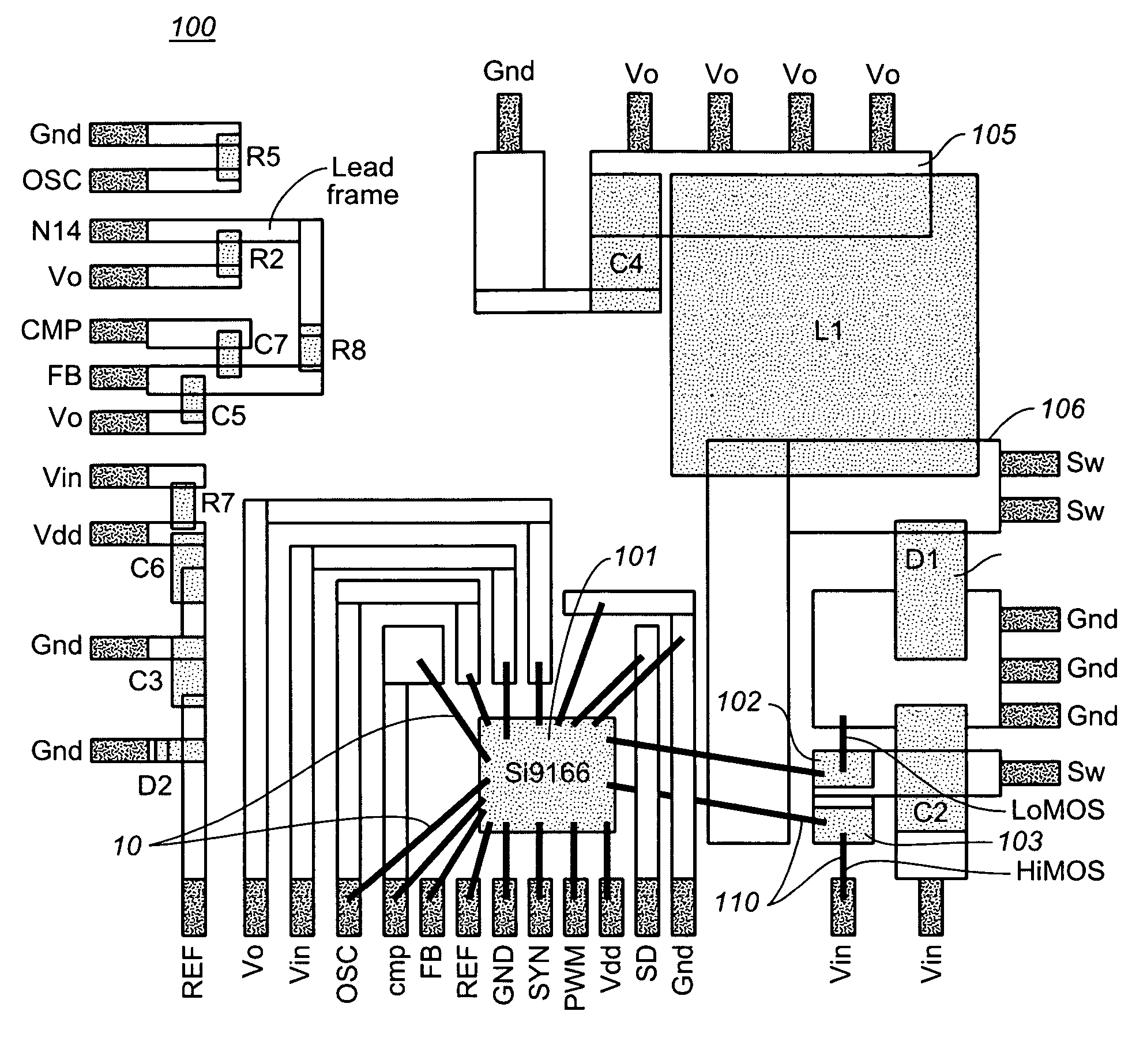
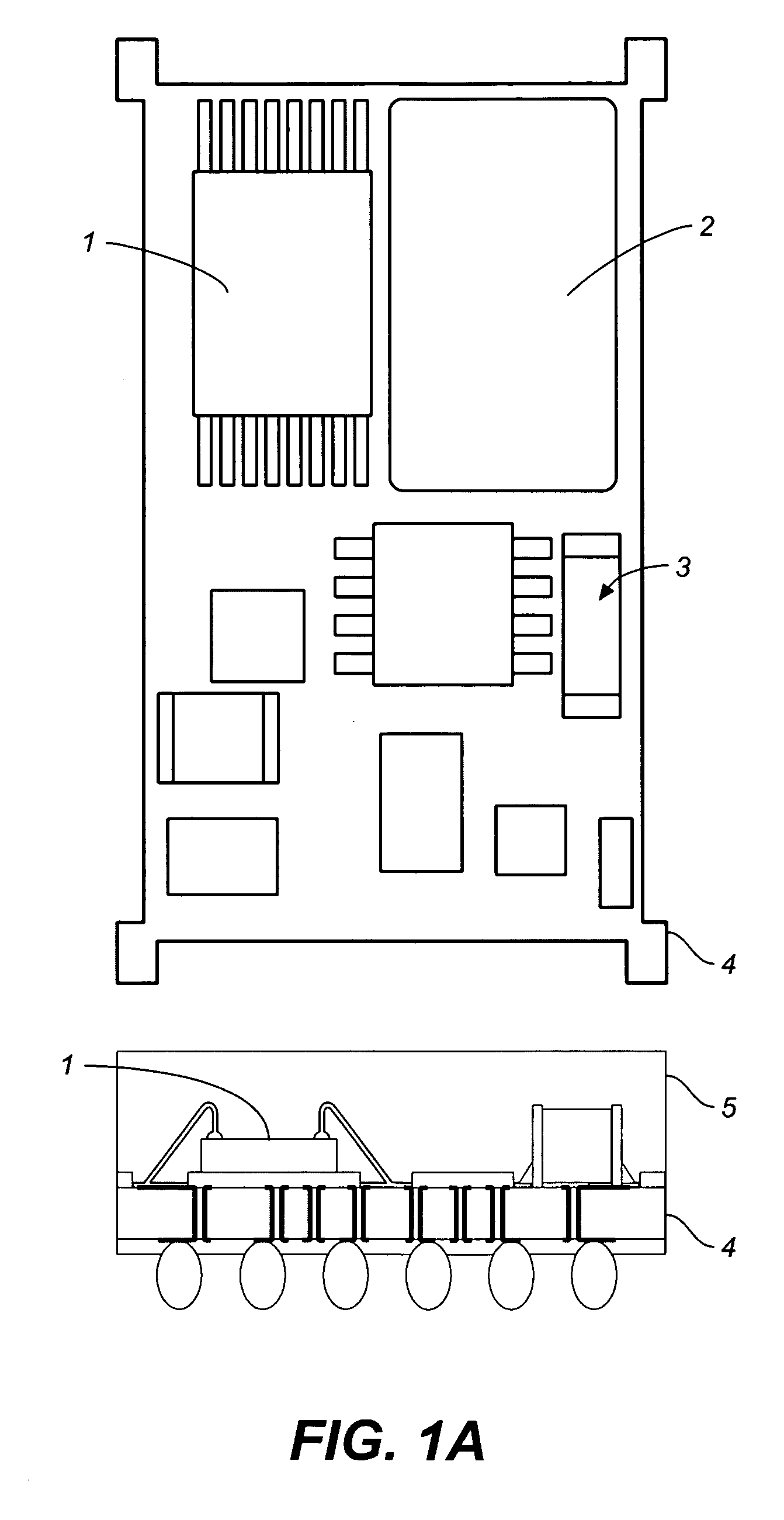
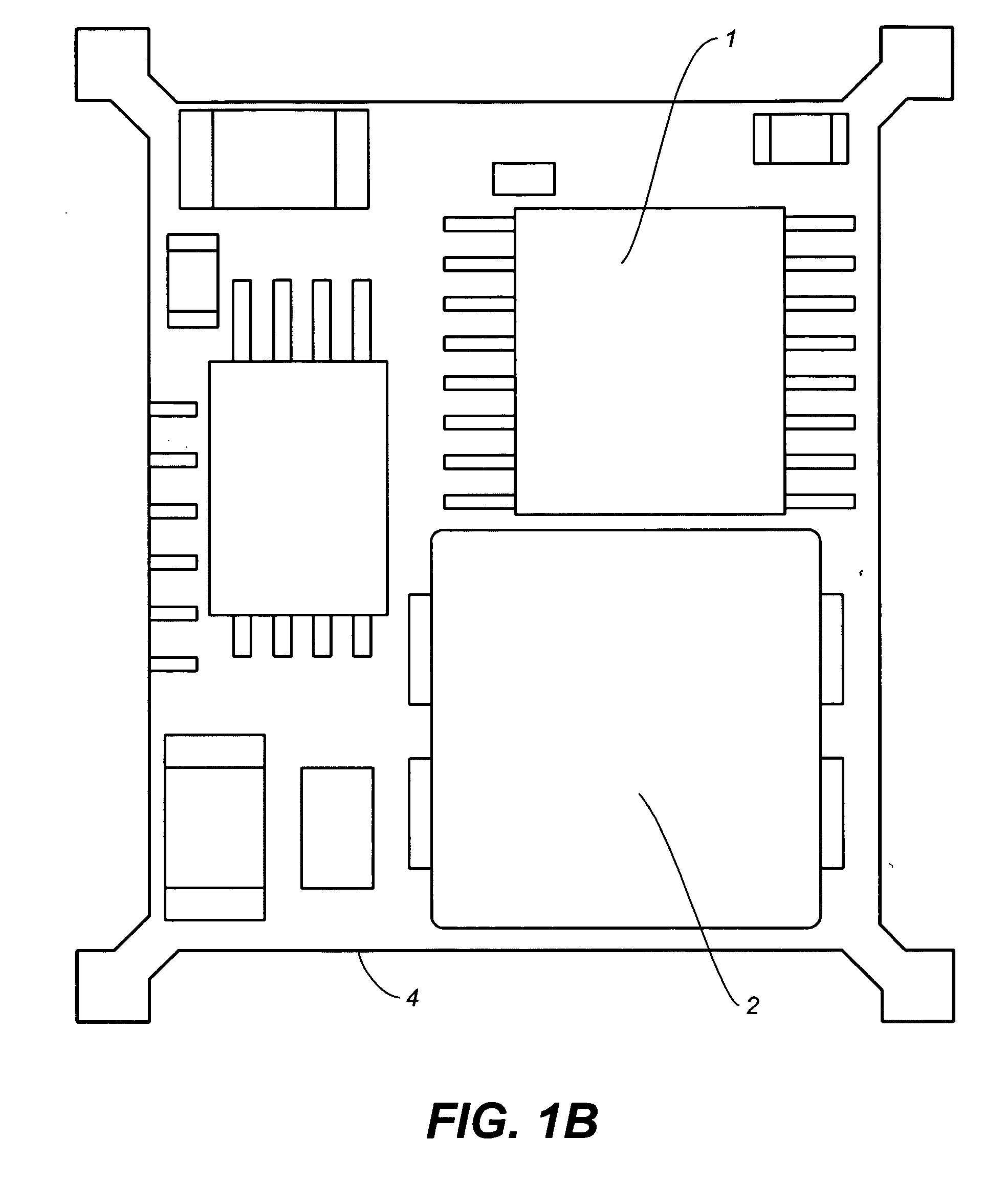
[0023] According to embodiments of the present invention, a standard surface mount package (SMP) is used with exposed metal bottom. The package may employ a copper lead frame to replace a multilayer FR4 substrate material (PCB) and the BGA connections. As a result, the assembly process is simplified and the product cost is reduced. In addition and the performance and reliability of the DC-DC converter is greatly enhanced.
[0024] The use of SMP has many advantages. The copper lead frame in the package is much thicker than that used in the MCM FunctionPAK®. Therefore, the parasitic resistance is significantly reduced compared to the conventional FunctionPAK®. Another advantage is to use metal (e.g., copper) clips on the source and drain of the MOSFET that improve thermal and electrical performance of the MOSFET. The metal clips can also be used on the diode. Also, SMP can handle much more current than MCM FunctionPAK®, because higher current causes more power loss, which cannot be dissipated by the high thermal resistivity of MCM FunctionPAK® construction.
[0025] Moreover, SMP can produce higher efficiency because it significantly reduces the parasitic inductance and the related switching loss, and it has good thermal performance. Also, SMP has higher power density because its good thermal performance can dissipate more power and it is more compact because the silicon dice are packageless. Also, SMP can make the circuit operate at higher switching frequency because it reduces the switching loss and it has much lower thermal resistivity.
[0026] SMP eliminates the internal packaging requirements of the electrical components. Without the internal package, the bare circuit components will have better thermal performance due to the high thermal conductivity of the lead frame and better electrical performance due to the less parasitic inductance. In addition, SMP can lead to less cost because there is no need for internal package.

Problems solved by technology

Also, SMP can handle much more current than MCM FunctionPAK®, because higher current causes more power loss, which cannot be dissipated by the high thermal resistivity of MCM FunctionPAK® construction.

Method used


Image

  • Complete power management system implemented in a single surface mount package
  • Complete power management system implemented in a single surface mount package
  • Complete power management system implemented in a single surface mount package

Examples


Embodiment Construction

[0048] Reference will now be made in detail to the preferred embodiments of the present invention, complete power management system implemented in a single surface mount package, examples of which are illustrated in the accompanying drawings. While the invention will be described in conjunction with the preferred embodiments, it will be understood that they are not intended to limit the invention to these embodiments. On the contrary, the invention is intended to cover alternatives, modifications and equivalents, which may be included within the spirit and scope of the invention as defined by the appended claims. Furthermore, in the following detailed description of the present invention, numerous specific details are set forth in order to provide a thorough understanding of the present invention. However, it will be recognized by one of ordinary skill in the art that the present invention may be practiced without these specific details. In other instances, well-known methods, proce...


PUM


Abstract

A complete power management system implemented in a single surface mount package. The system may be drawn to a DC to DC converter system and includes, in a leadless surface mount package, a driver / controller, a MOSFET transistor, passive components (e.g., inductor, capacitor, resistor), and optionally a diode. The MOSFET transistor may be replaced with an insulated gate bipolar transistor, IGBT in various embodiments. The system may also be a power management system, a smart power module or a motion control system. The passive components may be connected between the leadframe connections. The active components may be coupled to the leadframe using metal clip bonding techniques. In one embodiment, an exposed metal bottom may act as an effective heat sink.

Description

RELATED APPLICATIONS [0001] This Application claims benefit of U.S. Provisional Patent Application Ser. No. 60 / 696,037, attorney docket VISH-8755. PRO, filed Jul. 1, 2005, entitled “Complete Power Management System Implemented Using Leadless Surface Mount Package with Exposed Metal Bottom” to Owyang et al., which is hereby incorporated herein by reference in its entirety. [0002] This Application is related to U.S. Pat. No. 6,066,890, issued May 23, 2000, entitled “Separate Circuit Devices in an Intra-Package Configuration and Assembly Techniques,” to Tsui and Kasem, which is hereby incorporated herein by reference in its entirety.BACKGROUND OF THE INVENTION [0003] 1. Field of the Invention [0004] Embodiments of the present invention are directed toward the field of integrated circuit devices and packaging related to power management systems. [0005] 2. Related Art [0006] Varieties of integrated circuits are commercially available to facilitate power management tasks, for example, to ...

Claims


Application Information

Patent Timeline
Patent Type & Authority Applications(United States)
IPC IPC(8): H01L23/34
CPCH01L23/36H01L2924/1305H01L24/49H01L25/16H01L2224/48091H01L2224/48227H01L2224/48247H01L2224/48465H01L2224/49171H01L2224/49175H01L2224/73265H01L2924/01013H01L2924/01014H01L2924/01029H01L2924/01033H01L2924/0106H01L2924/01075H01L2924/01078H01L2924/01079H01L2924/01082H01L2924/13055H01L2924/13091H01L2924/14H01L2924/15311H01L2924/19041H01L2924/19105H01L2924/30107H02M3/00H05K1/0206H05K1/0218H05K1/141H05K1/181H05K3/202H05K3/284H05K3/3436H05K2201/10166H01L23/49861H01L2924/15747H01L2924/10253H01L2224/32245H01L2224/48137H01L2924/014H01L2924/01006H01L2224/32225H01L24/48H01L2924/00014H01L2924/00H01L2924/00012H01L2924/15787H01L2924/12042H01L24/73H01L2924/181G05F3/08H02M3/003H01L2224/45099H01L2224/05599H05K7/205H05K7/20409H02M3/04
Inventor OWYANG, KINGKASEM, MOHAMMEDBAI, YUMINGKUO, FRANKMAO, SENKUO, SAM
Owner VISHAY SILICONIX LLC
Learn More