Dual cure compositions, methods of curing thereof and articles therefrom

a composition and composition technology, applied in the field of dual cure compositions and curing methods, can solve the problems of short work-life and long cure time of most traditional thermally cured reactive formulations, and the formation of thick sections by curing of thermoset resins (, monomers)

Inactive Publication Date: 2007-03-22
GENERAL ELECTRIC CO
View PDF48 Cites 39 Cited by
  • Summary
  • Abstract
  • Description
  • Claims
  • Application Information

AI Technical Summary

Problems solved by technology

Formation of thick sections by curing of thermoset resins (sometimes referred to hereinafter as curable monomers) has been generally problematic.
Most traditional thermally cured reactive formulations have short work-life and long cure time.
On the other hand, photocured formulations have long work-life and are capable of rapid cure, but curing is limited by the penetration depth of UV light, especially in materials with high levels of fillers which absorb or block UV light, such as in

Method used


Image

  • Dual cure compositions, methods of curing thereof and articles therefrom
  • Dual cure compositions, methods of curing thereof and articles therefrom
  • Dual cure compositions, methods of curing thereof and articles therefrom

Examples


example 1

[0043] A formulation comprising DION® 9800-05 vinyl ester resin, 1.2% MEKP, 0.2% cobalt naphthenate, 0.1% dimethyl aniline, and 1% IRGACURE® 819 photoinitiator placed between glass plates was cured by exposure to 400W UV-A portable arc lamp for 5 minutes, after which the UV lamp was turned off. A glass laminate was obtained that was 3.2 millimeters (mm) thick.

[0044] The resin formulations (abbreviated “Form.”) used in additional examples are shown in Table 1. Component amounts are reported in parts by weight.

TABLE 1Form.Form.Form.Form.Form.Component(I)(II)(III)(IV)(V)Curable monomer10010010000Phosphine oxide10100MEKP-9H1.21.2000Co naphthenate0.20.2000Dimethyl aniline0.10.10002,4-pentanedione0.20.2000UVACURE ® 15000001000UVACURE ® 160000010Epoxy laminating0000100resinAmine hardener000035

example 2

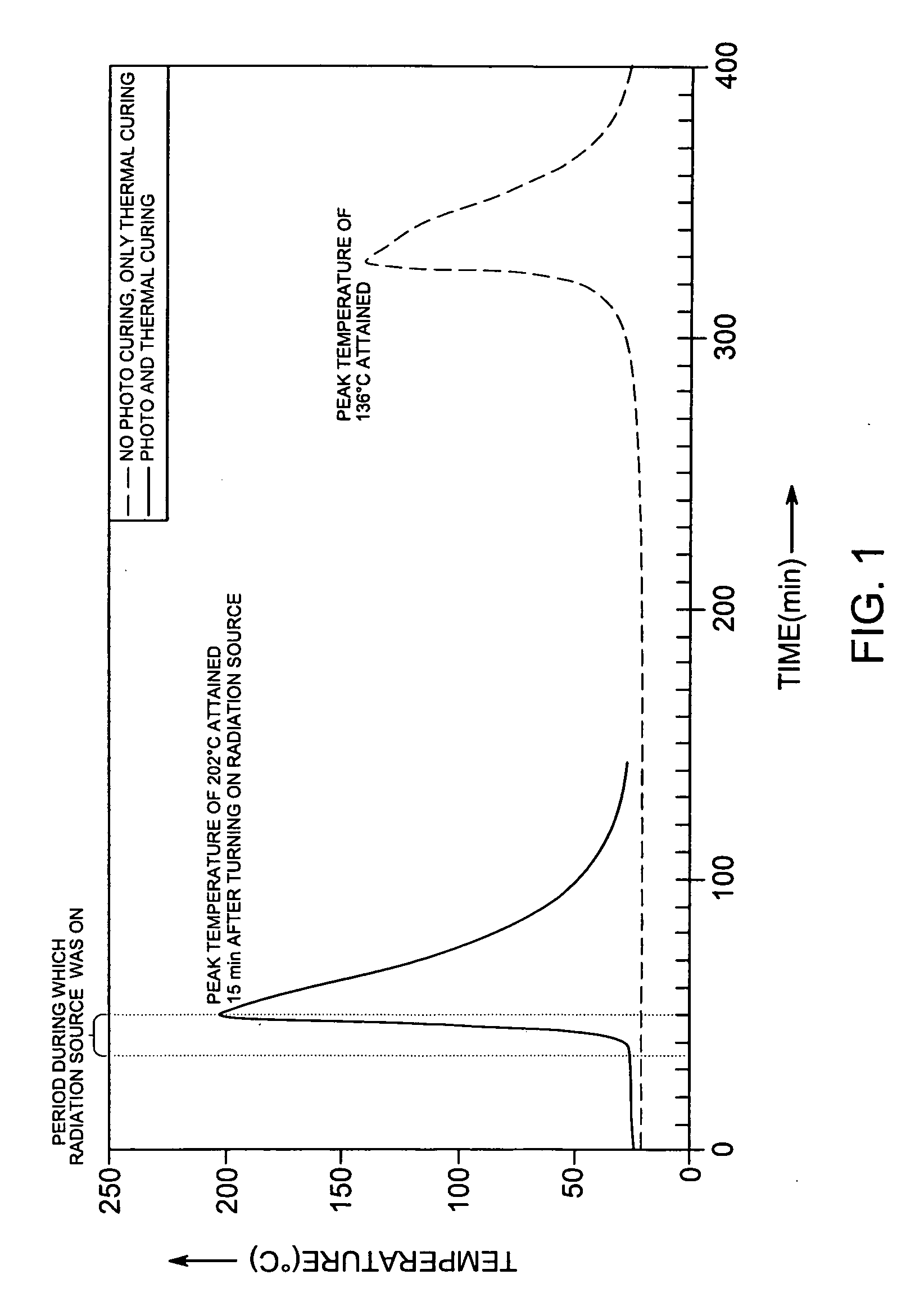
[0045] Two glass jars (each 5 centimeters diameter×4.4 centimeters height) were separately filled with 70 gm of formulation (I) in Table 1. A thermocouple was placed in the center of each glass jar to measure temperature rise with time. After 35 minutes, the radiation source UV-A 400W was turned on to illuminate one of the jars for 15 minutes, after which it was turned off. The temperature increased quickly and reached a peak value of 202° C. As a comparative example, the same formulation (I) was allowed to cure in the second jar without any UV radiation. The temperature in the second jar did not begin to increase until 300 minutes and the temperature finally reached 136.6° C. peak temperature at 330 minutes. FIG. 1 shows the temperature profile at the center of the formulation of each jar as determined by the thermocouples. This demonstrated that the formulation and method of the invention can achieve the cure on demand upon UV radiation exposure at any time between time zero and 3...

example 4

[0047] Carbon Fiber Composite Samples: A carbon fiber composite formed by using a 5 cm×10 cm carbon fiber fabric (TORAYCA® T700SC-12K-50C, 400 grams) comprising 3 plies formed by hand lay-up and wet laminated with formulation (I). The formulation was cured by exposure to UV radiation from a 400W UV-A lamp for 10 minutes, after which the UV lamp was turned off. The cured thickness was found to be 2.5 mm and was found to have solidified throughout the sample. This example demonstrates the dual cure composition overcomes the limitation of the UV light penetration through carbon fiber composites.


PUM

PropertyMeasurementUnit
Percent by massaaaaaaaaaa

Abstract

Disclosed herein are dual cure compositions, methods to cure dual cure compositions, the dual cure compositions comprising at least one filler, at least one curable monomer comprising at least one of an ethylenic unit or cyclic ether unit or mixture thereof; at least one photoinitiator; and at least one thermal initiator. The method comprises the step of photocuring by exposing the compositions to radiation to at least partially photocure the composition, which in turn generates an exotherm which initiates thermal curing. The methods may be used to make cured thick compositions and sandwich structures. Articles made by the methods are also described.

Description

BACKGROUND [0001] The invention relates generally to dual cure compositions, methods of curing, and resulting articles. [0002] Formation of thick sections by curing of thermoset resins (sometimes referred to hereinafter as curable monomers) has been generally problematic. Most traditional thermally cured reactive formulations have short work-life and long cure time. On the other hand, photocured formulations have long work-life and are capable of rapid cure, but curing is limited by the penetration depth of UV light, especially in materials with high levels of fillers which absorb or block UV light, such as in thick section composites, composite sandwich structures, and carbon fiber composites, thus resulting in uncured or incompletely cured portions. Curing thick carbon fiber composites has been demonstrated with e-beam technology. However, e-beam uses a high energy source which requires high cost capital investment. [0003] The problems described have been addressed by the use of c...

Claims


Application Information

Patent Timeline
IPC IPC(8): C08F2/50
CPCB32B5/18B32B5/26B32B5/28B32B9/00B32B17/04B32B27/04C08J2363/00B32B27/30C08F2/48C08K3/36C08K7/14C09D4/00C08J5/24B32B27/12C08J5/04
Inventor YANG, WENLIANG PATRICKLIN, WENDY WEN-LINGFURUTA, PAUL TAKAO
Owner GENERAL ELECTRIC CO
Why Eureka
Try Eureka