Sealing device

a sealing device and sealing wire technology, applied in the direction of presses, manufacturing tools, electric/magnetic/electromagnetic heating, etc., can solve the problems of difficult maintenance (e.g., heater wire replacement) and high cost, and achieve the effect of avoiding winding and breakage after a few revolutions

Inactive Publication Date: 2007-03-29
PREGIS INTELLIPACK CORP
View PDF87 Cites 33 Cited by
  • Summary
  • Abstract
  • Description
  • Claims
  • Application Information

AI Technical Summary

Benefits of technology

[0019] The present invention is directed at problem reduction relative to prior art sealers such as the edge sealers described above, by avoiding, for example, some of the complexities associated with the coil wire wrap arrangement like that in the above noted '20

Problems solved by technology

A problem associated with the '208 patent approach is that it requires a rotating electrical contact to supply power to the edge seal wire.
Since the edge seal wire is rotating with the nip roll, direct wire connections from the edge seal wire to the non-rotating control board presents the potential for wind up and breakage after a few revolutions.
This problem is addressed with a rotating electrical union, which is quite expensive and has many failure modes of its own.
Also, maintenance (e.g., heater wire replacement) is difficult with this embodiment as can be seen by the high finger dexterity requirement associated with removing and replacing wires on its substrates.
In addition, even with a highly skilled person with good dexterity the switching out of a defective wire for a new one is time consuming and thus also undesirable to a user from a manufacturing “down time” efficiency standpoint.
A disadvantage of this commercialized embodiment of the '638 design is its short life in comparison to other designs.
A further difficulty associated with the prior art designs is seen in the difficulty of forming and maintaining good seal production as opposed to weak or defective seals due to improper bonding temperature or surface c

Method used


Image

  • Sealing device
  • Sealing device
  • Sealing device

Examples


embodiment 91

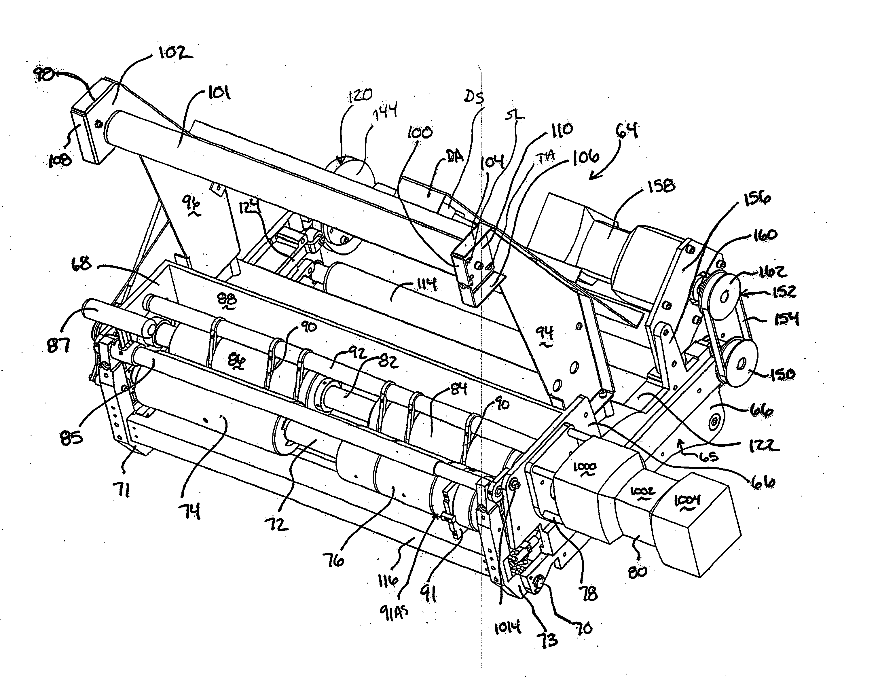
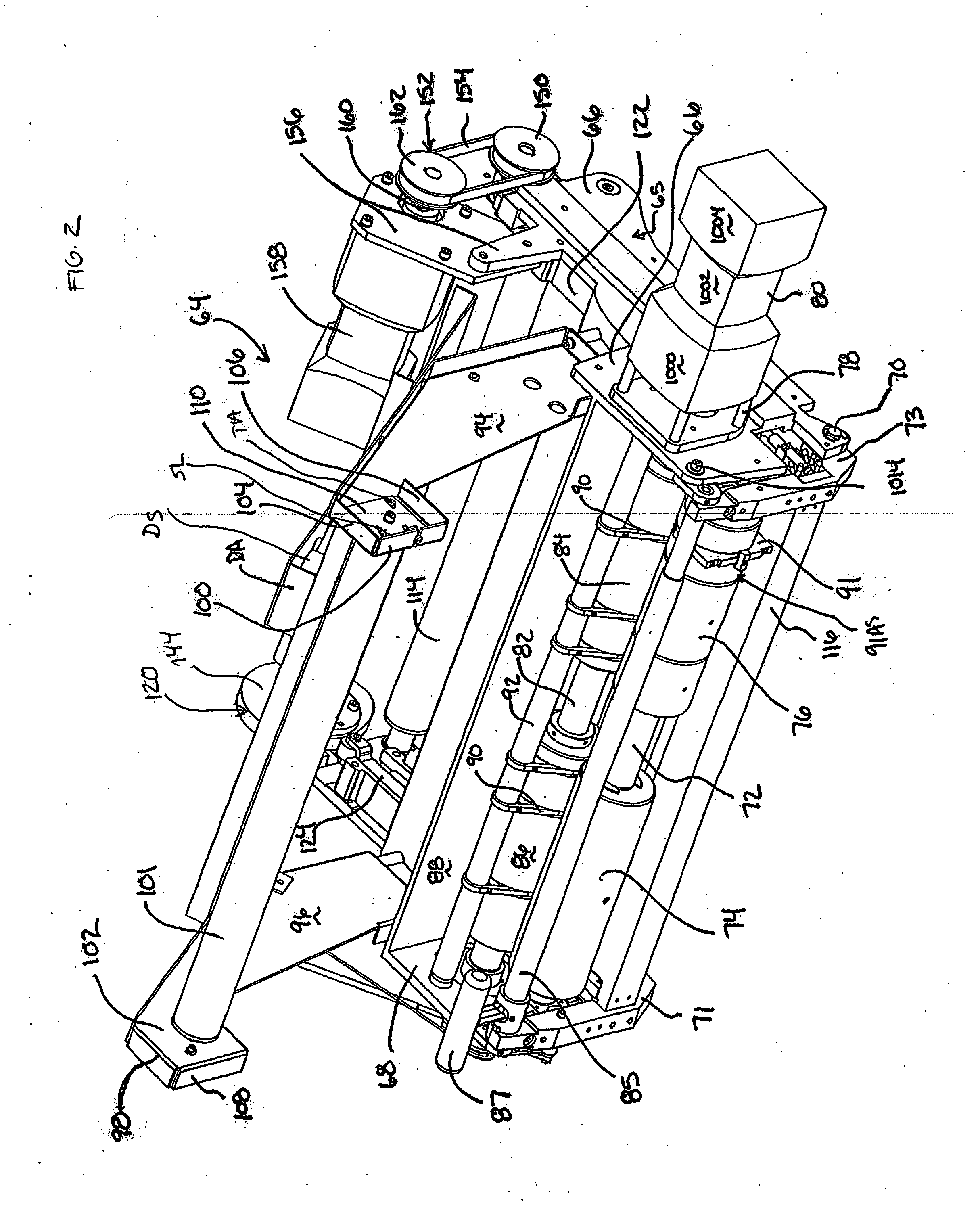
[0156] FIGS. 8 to 67 illustrate in greater detail an embodiment of edge sealer assembly combination 91AS (with two different edge seal types referenced as 91 and 91′ with the letter “A” added to represent components of the second edge sealer assembly embodiment 91′). Edge sealer assembly combination 91AS comprises first and second sub-rollers 1100 and 1102 and edge sealer assembly 91 having edge sealer (or arbor assembly) 1106 on the film contact side of the driven roller and support base (or arbor base) 1108 on the opposite side. FIG. 14 shows each sub-roller 1100 and 1102 having a pocket cavity 1110 and 1112. FIGS. 18 and 20 illustrate sub-roller 1102 with pocket cavity and with the cavity interior surface 1114 having a pair of screw holes 1116 spaced circumferentially (diametrically) around it, that open out at the other end as shown in FIG. 18. Thus, edge seal roller 1102, which is positioned on the side of the edge seal assembly 91 that is closest to the center of elongation of...

third embodiment

[0196]FIG. 68 illustrates third embodiment edge sealer assembly 91″ of the present invention which, in a preferred embodiment, is configured as an arbor assembly like the two above described first and second edge sealer embodiments utilized with roller mounts in edge seal assembly combinations 91AS′ or some alternate mounting means to place the sealing device at the desired position relative to the film material being sealed. Edge sealer assembly 91″ comprises edge sealer 310 housing body or “arbor body”311 which, in the illustrated preferred embodiment, is formed of an electrically conductive material (e.g. steel) and as a monolithic body with a film-side peripheral edge 3100. A steel arbor body also provides the benefits of low flexibility (e.g., steel, as in a hardened steel, is in the order of 100 times stiffer than “Acetal” plastic). Edge 3100 is preferably formed of an overall convex contour with a less convex or planar intermediate face or presentation section 3101 being prov...


PUM

PropertyMeasurementUnit
Lengthaaaaaaaaaa
Fractionaaaaaaaaaa
Fractionaaaaaaaaaa

Abstract

A sealing device with film sealer for localized heating to bond film material as in one having a high temperature resistance (e.g., ceramic) substrate with a properly sized groove for receiving a heater element as in a flat faced wire band in a tight, flush to adjacent film presentation surface arrangement. A stacked ceramic plate set with a wire band received within a groove defined by a smaller height intermediate stack insert is a suitable substrate. The band is retained flush by a positioner fixer system that securely locks down one end for band tightening and the other end is provided at an access location of said housing body for clamping and tensioning the heater element into ready for use position within the groove. The edge sealer is suited for use as a product-in-bag sealing device (products such as air, foam, foodstuff, etc.) with the heater element placed in contact with film material to form a seal. A drag seal arrangement, where film layers are drawn past a fixed or adjustably mounted heater element to achieve bonding of one plastic film layer to another, is an example. The invention avoids repeated sealer replacement particularly when the film source (e.g., a film roll) has yet to run out.

Description

CROSS-REFERENCE TO RELATED APPLICATIONS [0001] The present invention is a continuation-in-part of U.S. Ser. No. 11 / 623,100 filed Jul. 22, 2003, which claims the priority of provisional application 60 / 468,988 filed May 9, 2003, with each of these being incorporated herein by reference.FIELD OF INVENTION [0002] The present invention relates to a sealing device, with a preferred embodiment being a sealer with means for localized heating to bond film material as in a resistance heating element applied to film layers such as those used in bag formation. BACKGROUND OF THE INVENTION [0003] Many sealing mechanisms have been created including sealing mechanisms such as those used in “Foam-In-Bag”, “Air-In-Bag” and “Food (or other Product types)-In-Bag” manufacturing devices. Many endeavor to use a sealing wire, heated by electrical resistance, which rolls or drags over the material being sealed. Other sealing techniques have been attempted, including the use of hot melt glues, pressures sens...

Claims


Application Information

Patent Timeline
IPC IPC(8): B30B15/34
CPCB29C65/7894B29C66/961B29C66/43B29C66/80B29C66/8167B29C66/1122B29C66/91213B29C66/91315B29C66/91313B29C66/91212B29C66/81871B29C65/223B29C66/91231B29C65/228B29C65/229B29C66/91651B29C66/91421B29C66/91431B29C66/91655B29C66/81422B29C66/81427B29C66/8122B29C65/00B29K2909/02B29K2827/18B29C65/224B29C66/439B29C66/71B29K2023/065
Inventor BERTRAM, GEORGEWALKER, DOUGLAS
Owner PREGIS INTELLIPACK CORP
Why Eureka
Try Eureka