
Microwave generator and apparatus using the same

a generator and microwave technology, applied in the field of microwave generators and apparatuses, can solve the problems of inability to communicate wirelessly in the ism band, hinder the reduction in the size and weight of microwave generators using magnetron for oscillating sources have been incapable of meeting this requirement, so as to reduce the size and weight, prevent unwanted radiation, and improve the effect of signal purity

Inactive Publication Date: 2007-03-29
SEIKO EPSON CORP
View PDF3 Cites 3 Cited by
  • Summary
  • Abstract
  • Description
  • Claims
  • Application Information

AI Technical Summary

Benefits of technology

[0010] An advantage of the invention is to provide a microwave generator that is reduced in size and weight and capable of preventing unwanted radiation. It is another advantage of the invention to provide an apparatus using the microwave generator.
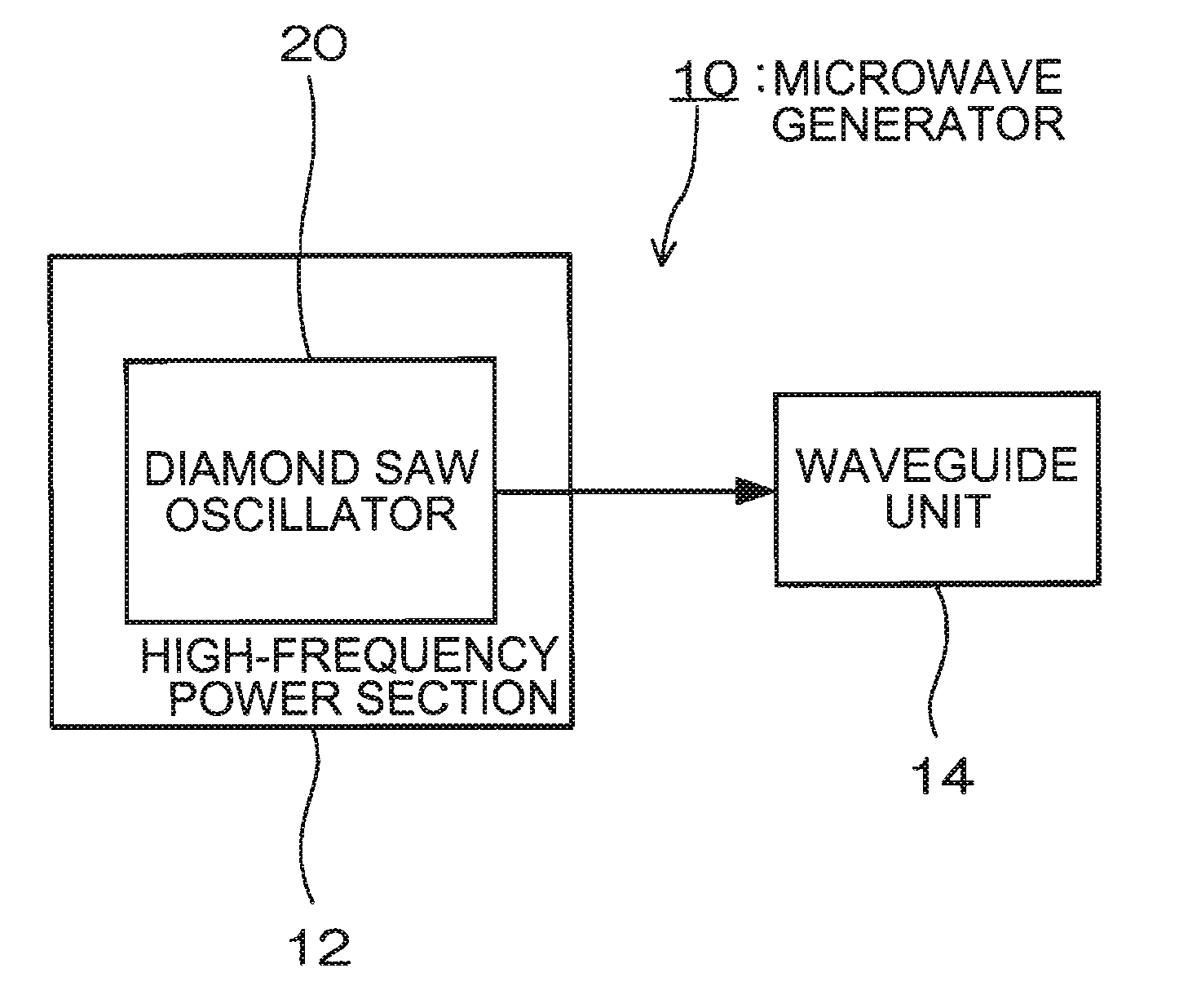
[0011] According to a first aspect of the invention, a microwave generator has a diamond SAW oscillator, a high-frequency power section that outputs the high-frequency signals outputted from the diamond SANY oscillator to a subsequent stage and a waveguide unit that emits the high-frequency signals inputted from the high-frequency power section in the form of microwave.
[0012] The diamond SAW oscillator is capable of outputting only those high-frequency signals that correspond to the resonance frequency of the SAWN, being excited on the substrate, without outputting signals corresponding to any frequency other than the resonance frequency and without oscillating with an abnormal frequency. Therefore, use of the diamond SAW oscillator improves the signal purity. Furthermore, guiding a high-frequency signal from the high-frequency power section to the waveguide unit will allow radiation of only the radio wave corresponding to the frequency of the high-frequency signals, namely only microwave, thereby preventing unwanted radiation. Consequently, the microwave generator is capable of reducing noise, thereby preventing adverse effects on apparatuses using the ISM band.
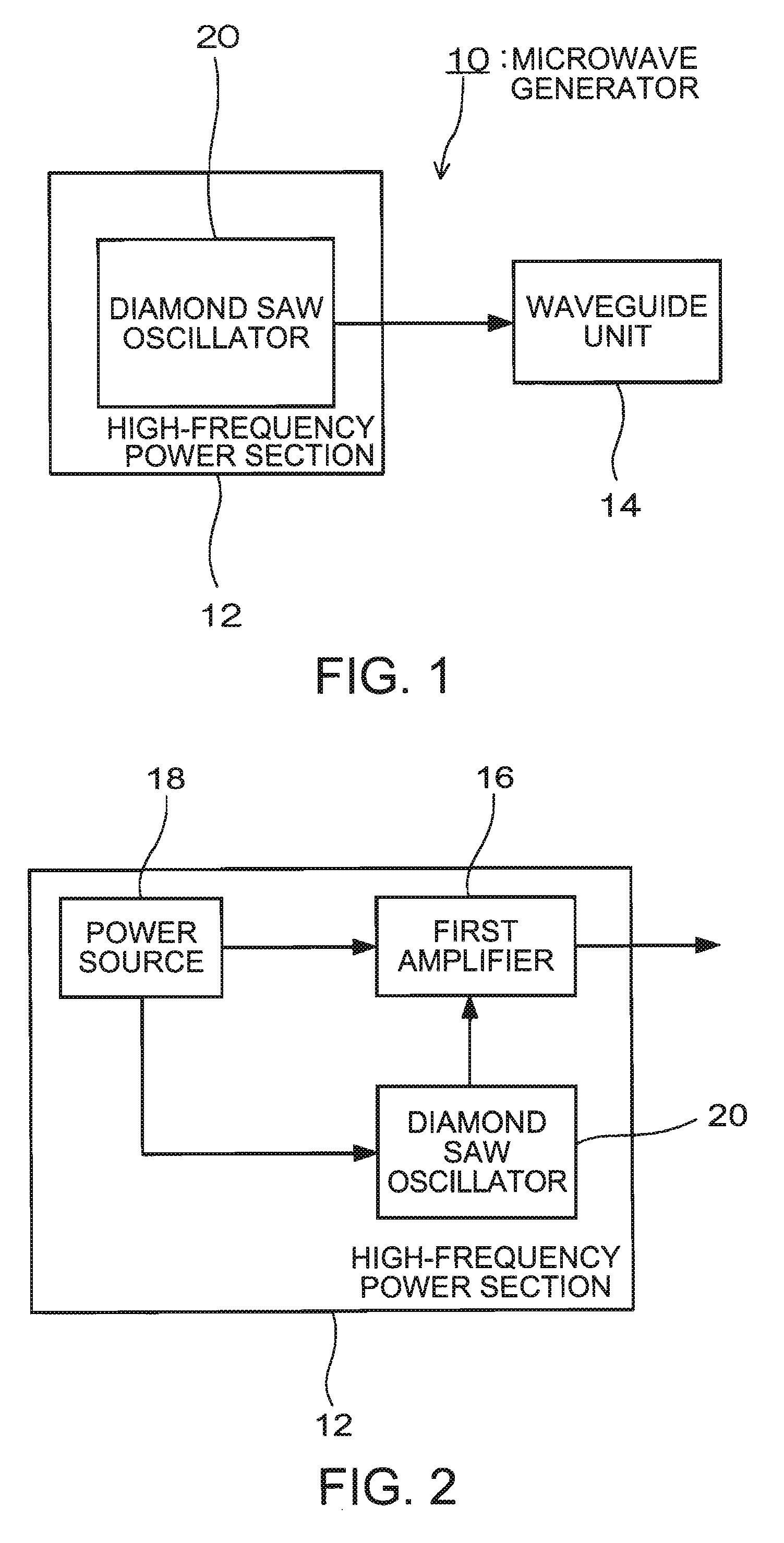
[0013] It is preferable that the high-frequency power section of the microwave generator includes: the diamond SARWS oscillator that outputs high-frequency signals; a first amplifier that amplifies and outputs the high-frequency signals inputted from the diamond SAW oscillator; and a power source that supply power to the diamond SAW oscillator and to the first amplifiers.
[0014] Through the first amplifier that is provided subsequent to the diamond SAW oscillator, the high-frequency signals outputted from the diamond SAW oscillator can be amplified, resulting in their magnified signal strength.
[0015] In this case, the high-frequency power section of the microwave generator may include: the diamond SAW oscillator that outputs the high-frequency signals; a plurality of first amplifiers that are connected in parallel to the diamond SAW oscillator, each inputting the high-frequency signals from the diamond SAW oscillator; an adder that is connected subsequent to the first amplifiers and inputs and adds the high-frequency signals outputted from the first amplifiers in order to subsequently output the added high-frequency signals; and a power source that supplies power to the diamond SAW oscillator and to the first amplifiers.

Problems solved by technology

Consequently, the magnetron generates unwanted radiation, thereby giving rise to a problem that other apparatuses are adversely affected in such a way that they become incapable of communicating wirelessly in using the ISM band.
Also, since magnetron is large in size, it has so far hindered reduction in the size and weight of microwave generators using magnetron.
However, microwave generators using magnetron for the oscillating source have been incapable of meeting this requirement.
In addition, magnetron has also had some other problems including a significant amount of power consumed, poor frequency temperature behavior, and instability in outputted frequency, and so on.
However, LC oscillators and dielectric oscillators have had such problems as poor frequency temperature behavior, instability of outputted frequency, a significant amount of jitters and variability in the frequency between each oscillator.
On the other hand, PLL circuits and multiplier circuits have had problems including their large size that hinders size-reduction, the significant amount of power they consume and the significant amount of time they take in order to output the required frequency.
Furthermore, PLL circuits have an additional problem that they are incapable of outputting a required frequency if any unlocking occurs.

Method used


Image

  • Microwave generator and apparatus using the same
  • Microwave generator and apparatus using the same
  • Microwave generator and apparatus using the same

Examples


first embodiment

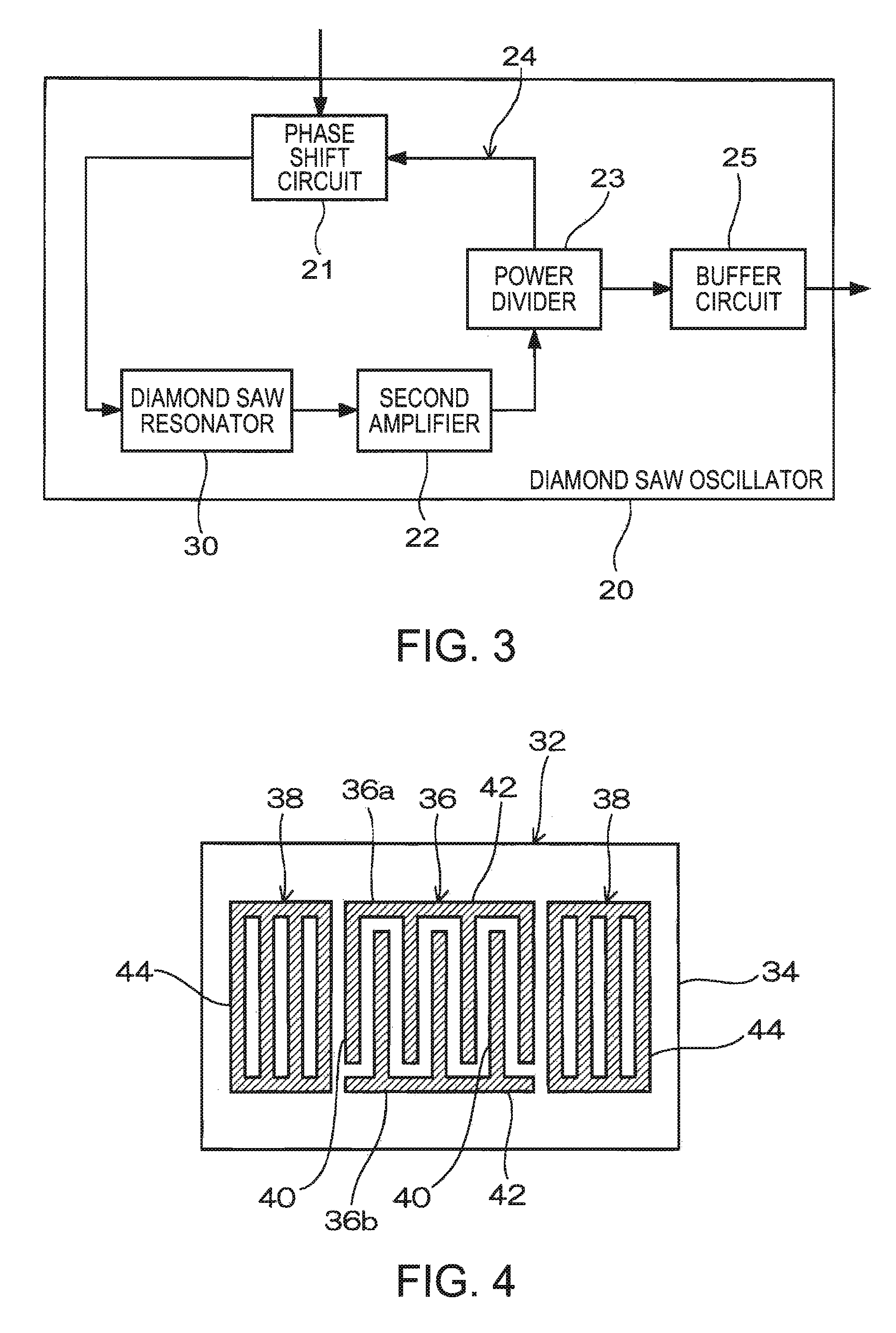
[0030] A microwave generator according to a first embodiment of the invention is shown in the block diagram in FIG. 1. The microwave generator 10 has a high-frequency power section 12 that includes a diamond surface acoustic wave (SAW) oscillator 20. The high-frequency power section 12 outputs high-frequency signals obtained in the diamond SAW oscillator 20 to a subsequent stage. The high-frequency signals are used to generate microwave. The microwave generator 10 includes a waveguide unit 14 that is connected subsequent to the high-frequency power section 12. The waveguide unit 14 inputs the high-frequency signals from the high-frequency power section to radiate the high-frequency signals in the form of microwave. The waveguide unit 14 may be an antenna, or may include an antenna and an isolator. Providing an isolator between the high-frequency power section 12 and the antenna prevents reflected waves generated in the antenna from returning to the high-frequency power section 12.

[...

second embodiment

[0042] A second embodiment of the invention describes a transformed example of the diamond SAW oscillator described in the first embodiment. The second embodiment will omit description of the components that are the same as in the first embodiment, providing them with the same numbers as in the first embodiment.

[0043]FIG. 6 is a block diagram of a high-frequency power section according to the second embodiment of the invention. The high-frequency power section 12 includes the diamond SAW oscillator 20, a plurality of the first amplifiers 16, an adder 50 and the power source 18. The power source 18 supplies power to the diamond SAW oscillator 20 and to each of the first amplifiers 16. The plurality of first amplifiers 16 are connected in parallel between the diamond SAW oscillator 20 and the adder 50. The high-frequency signals outputted from the diamond SAW oscillator 20 are inputted to each of the first amplifiers 16. The first amplifiers 16 amplify the high-frequency signals inpu...

third embodiment

[0045] In a third embodiment of the invention, an example of an apparatus using the microwave generator of the first embodiment or a microwave generator mounted with the diamond SAW oscillator of the second embodiment will be described. Therefore, the third embodiment will omit description of the components that are the same as in the first or the second embodiment, providing them with the same numbers as in the first or the second embodiment.

[0046]FIG. 7 is a block diagram of a plasma generator. The plasma generator 60 has a plasma-generating container 62 for containing microwave. The plasma-generating container 62 is supplied with a gas for generating plasma and connected with a vacuum pump (not illustrated) for depressurizing the inside of the plasma-generating container 62. The plasma generator 60 also includes the diamond SAW oscillator 20 and the microwave generator 10 having the high-frequency power section 12 that outputs the high-frequency signals outputted from the diamon...


PUM

PropertyMeasurementUnit
frequenciesaaaaaaaaaa
frequencyaaaaaaaaaa
poweraaaaaaaaaa

Abstract

A microwave generator comprises: a high-frequency power section that includes a diamond SAW oscillator and outputs a high-frequency signal outputted from the diamond SAW oscillator to a subsequent stage; and a waveguide unit that emits the high-frequency signal inputted from the high-frequency power section in a form of microwave.

Description

BACKGROUND [0001] 1. Technical Field [0002] The present invention relates to a microwave generator and an apparatus using the same. [0003] 2. Related Art [0004] The Industry Science Medical (ISM) band that takes advantage of microwave is utilized in a variety of apparatuses including heating units, plasma generating devices, communications equipments and radar systems. In order to radiate such microwave, some microwave generators use magnetron for the oscillating source. [0005] JP-A-9-265914 is a first example of related art disclosing a magnetron apparatus that includes a high-voltage noise filter. According to the example, a small and low-cost high-voltage noise filter can be obtained by: providing an insulating layer and a conductive layer on the surface of a coiled conductors providing another layer having a high withstand voltage between the conductive layer and the outer peripheral surface of the insulating layer near the end of the conductive layer, thus alleviating the elect...

Claims


Application Information

Patent Timeline
Patent Type & Authority Applications(United States)
IPC IPC(8): B23K9/00
CPCH05B6/68
Inventor KARASAWA, HIDEOMATSUMOTO, YOSHIAKIONUKI, MASAHIROSAKUMA, MASAYASU
Owner SEIKO EPSON CORP
Learn More