Determination of a channel estimate of a transmission channel
a technology of transmission channel and channel estimate, which is applied in the direction of transmission monitoring, dc level restoring means or bias distort correction, baseband system details, etc., can solve the problems of high interference, large and highly localized amplitude and phase shift of signals, and thermal noise, so as to improve the channel estimate for one channel, improve the channel estimate, and improve the estimate. the effect of accuracy
- Summary
- Abstract
- Description
- Claims
- Application Information
AI Technical Summary
Benefits of technology
Problems solved by technology
Method used
Image
Examples
first embodiment
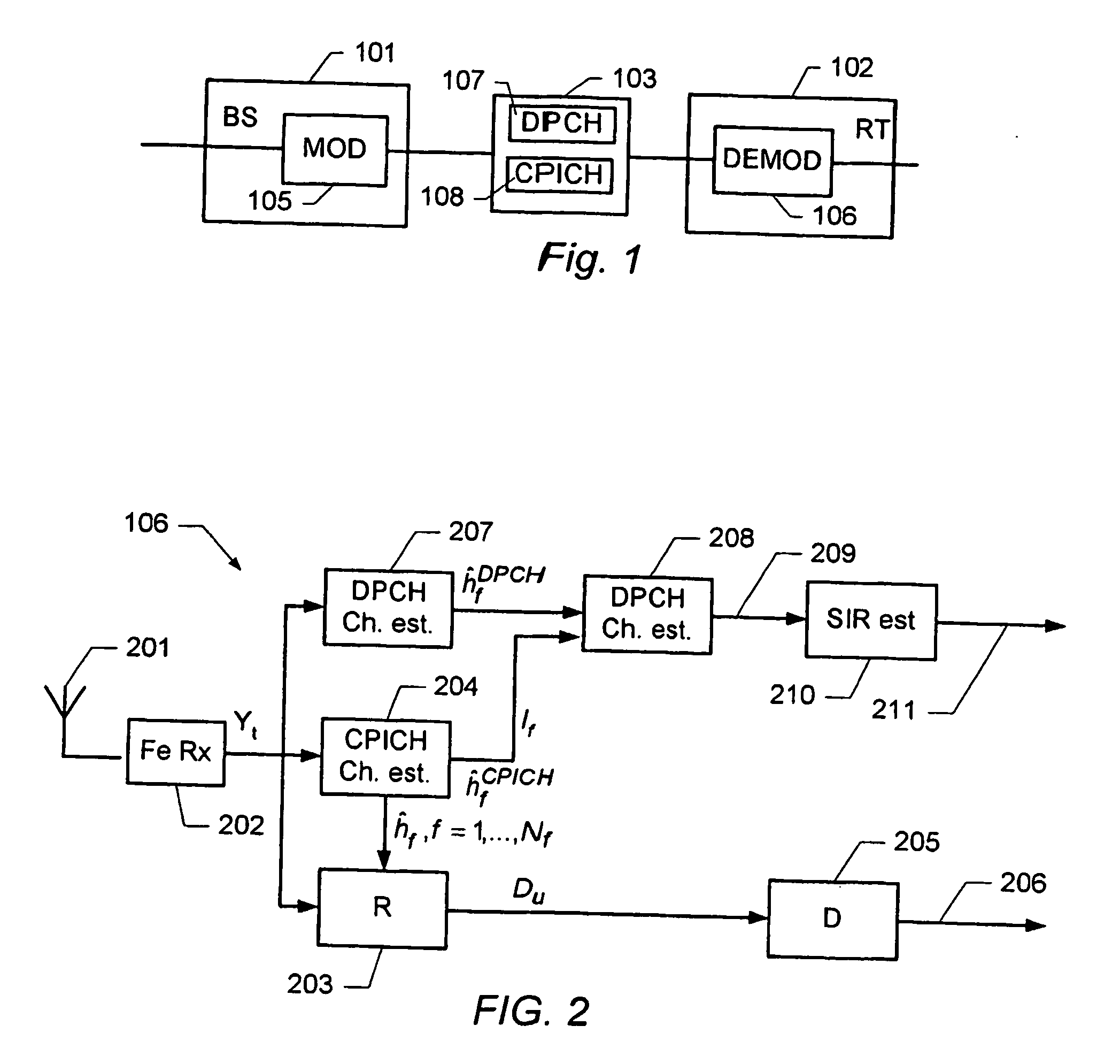
[0065]FIG. 2 schematically shows a block diagram of a receiver including an arrangement for estimating a SIR. The receiver, generally designated 106, comprises a front-end receiver 202 that down-converts and samples the received radio signal to a digital baseband signal Yt. The receiver 106 further comprises a dedicated channel estimation unit 207, a common pilot estimation unit 204, and a RAKE receiver 203, each of which receive the digital baseband signal Yt. The RAKE receiver uses several baseband correlators in the so-called fingers of the RAKE receiver in order to individually process several signal multipath components according to a corresponding propagation delay and channel estimate. The correlator outputs are combined to achieve improved communications reliability and performance (see e.g. “Digital Communications” 4th Edition, by John G. Proakis, McGraw-Hill, 2000). The RAKE receiver generates signal symbols Du which are fed to a decoder 205.
[0066] The channel estimation u...
second embodiment
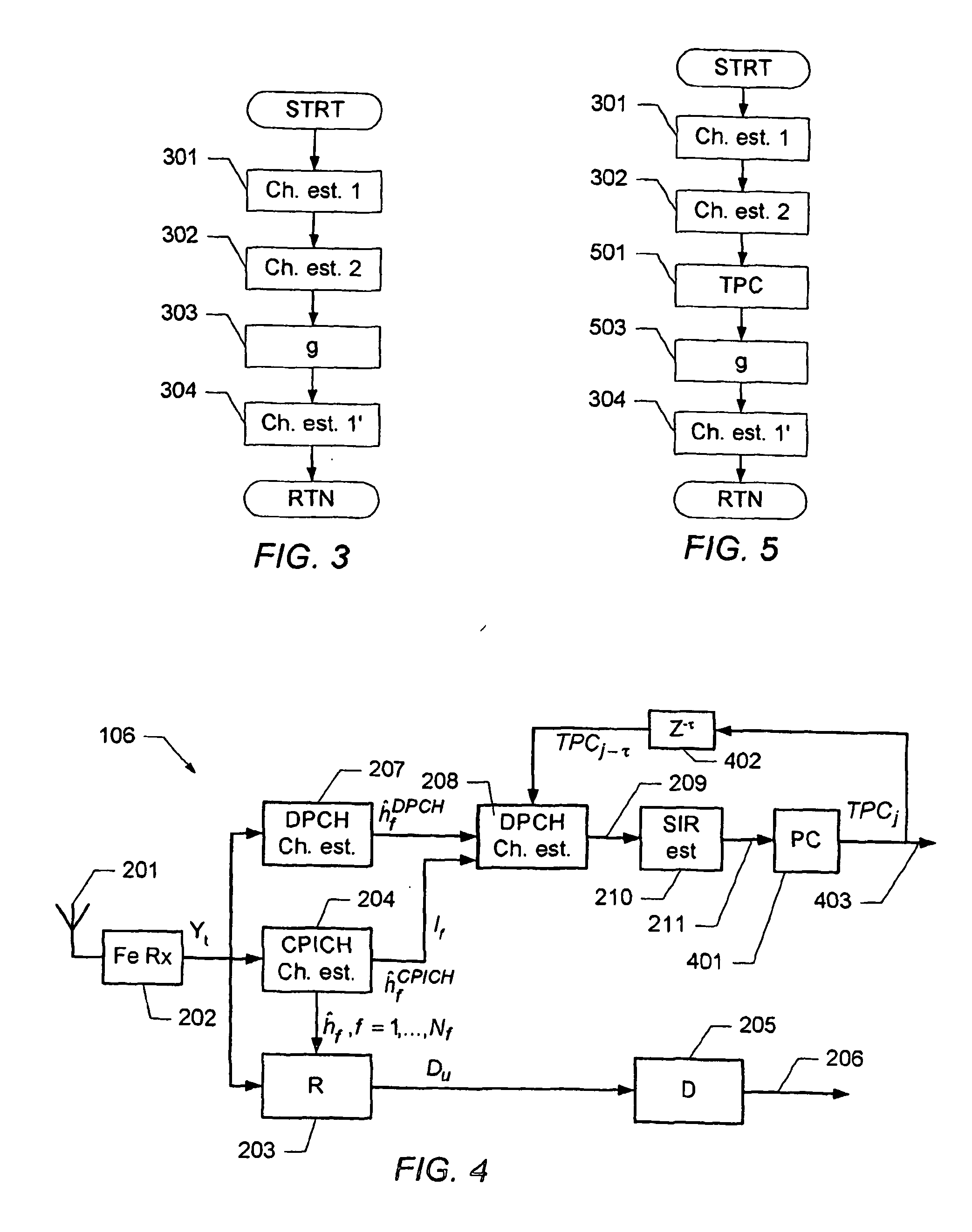
[0077]FIG. 4 schematically shows a block diagram of a receiver including an arrangement for estimating a SIR. According to this embodiment, the channel estimate is further based on power control commands of a power control loop. The receiver according to this embodiment is similar to the receiver described in connection with FIG. 2. The receiver further comprises a power control unit 401. The power control unit implements a closed loop power control of the power at which the receiver receives the communications signals on the DPCH. In particular, the transmitted power on the DPCH in slot j is changed by a factor 10ΔTPCTPCj−1 relative to a previous slot j−1. Here, ΔTPC is a fixed power increment set by the network, i.e. ΔTPC determines by which amount the power is incremented. In some communications networks, the value of ΔTPC is signaled to the receiver. However, in other systems this may not be the case. Furthermore, TPCj−τ represents a power control command determined by the recei...
third embodiment
[0088]FIG. 6 schematically shows a block diagram of a receiver including an arrangement for estimating a SIR. The receiver according to this embodiment is similar to the receiver described in connection with FIG. 2. According to this embodiment, the receiver further comprises a control unit 601 that receives information 602 from a higher layer (not explicitly shown) of the communications model implemented by the receiver. In one embodiment, the control unit receives information about the current radio access bearer (RAB), e.g. information about the slot formats, information about the number of pilot symbols in the dedicated channel, information about spreading factors, etc. Based on this information the control unit generates a control signal 603 which is fed into the channel estimation block 208 to control the channel estimation and / or the subsequent SIR estimation process.
[0089] For instance, if a low rate data channel with high spreading factor and few DPCH pilot symbols are used...
PUM
 Abstract
Description
Claims
Application Information
 - R&D
- Intellectual Property
- Life Sciences
- Materials
- Tech Scout
- Unparalleled Data Quality
- Higher Quality Content
- 60% Fewer Hallucinations
Browse by: Latest US Patents, China's latest patents, Technical Efficacy Thesaurus, Application Domain, Technology Topic, Popular Technical Reports.
© 2025 PatSnap. All rights reserved.Legal|Privacy policy|Modern Slavery Act Transparency Statement|Sitemap|About US| Contact US: help@patsnap.com


