Repair of damaged tissue on a bone site

Inactive Publication Date: 2007-03-29
XIROS
View PDF19 Cites 94 Cited by
  • Summary
  • Abstract
  • Description
  • Claims
  • Application Information

AI Technical Summary

Benefits of technology

[0036] Preferably, the delivery device is capable of being removably mounted, at its remote end, on a manually operable tool handle. The coupling between the tool handle and the delivery device preferably includes a bearing which permits (unnecessary) turning movement of the tool handle (during manipulation

Problems solved by technology

Such changes may result in the need for a total knee replacement which is particularly undesirable in young active individuals with a long life expectancy.
Furthermore implant revision procedures are both lengthy and very costly.
However, there are no donor sites in the knee with cartilage of a comparable thickness to that of the deficient site that can be described as ‘non-weight-bearing’ areas.
Furthermore, harvesting a large osteochondral plug from the solcus terminalis may cause the lateral meniscus to become lax and impair its load-bearing function.
While the OATS method provides a reasonable technique, including good instrumentation, for transplanting live autogenous grafts for repair of defects in cartilage, it involves introducing potentially damaging effects at other sites with the serious disadvantages discussed above.
In addition, harvesting a plug from a donor site creates a new damage in the knee articular surface.
For this reason, OATS would not be suitable for the repair of large defects.
The use of OATS for small repairs would probably limit the magnitude of the problem discussed above, but it would also limit the indication for using this technique.
There is a high probability of the chondrocytes

Method used


Image

  • Repair of damaged tissue on a bone site
  • Repair of damaged tissue on a bone site
  • Repair of damaged tissue on a bone site

Examples


Embodiment Construction

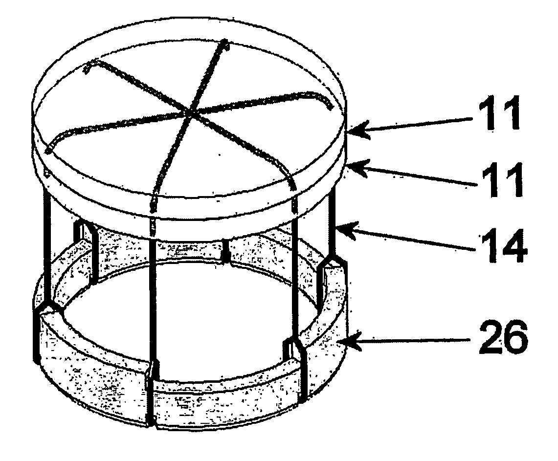
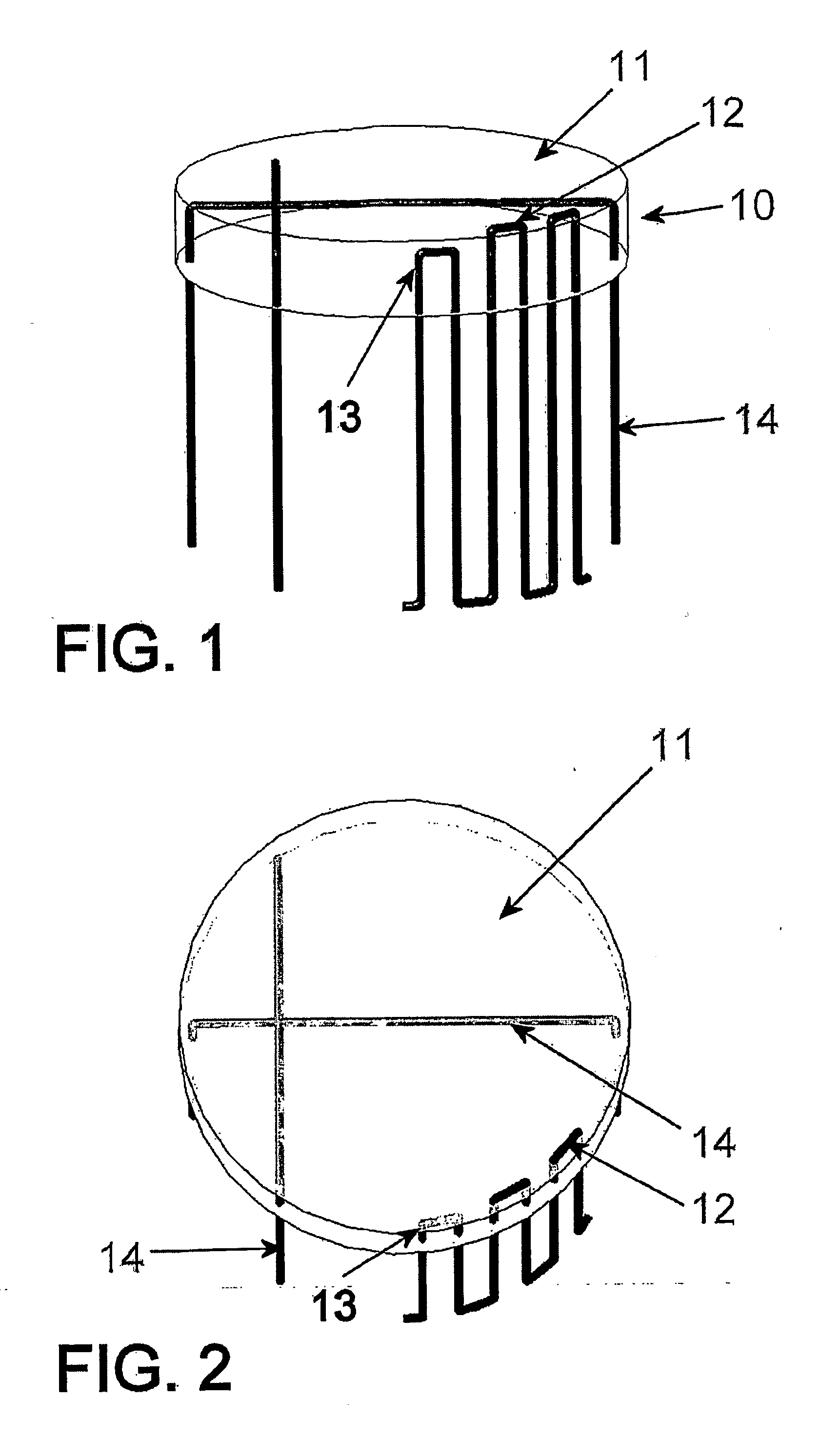
[0042] The improved device may comprise a pad made of woven or non-woven material, permanent or bioabsorbable when implanted in the body, which is connected to threads made of mono-filamentous- or multi-filamentous yarns, or sutures that are of permanent or bioabsorbable materials when implanted in the body. The threads can be connected to the pad through its substance either parallel to the surfaces of the pad or through the substance of the pad in a substantially perpendicular or inclined direction to the surfaces of the pad (as illustrated in FIG. 1 and FIG. 2), the thread ends (which can be in the form of loops or single ends or both) emerging near the periphery of the pad and projecting from the site where they emerge by a distance of say 30 millimetres (but can be longer or shorter), thus forming means of securing the pad in a narrow groove prepared to surround a repair site prepared as described above. A ring (matching in shape to that of the groove) is fitted into the groove...


PUM


Abstract

A repair kit for use in the repair of damaged cartilage present at or on the surface of a bone site in an animal or human, in which the damaged cartilage is removed from the site and a groove is formed about the site and into the bone prior to implantation of the repair kit. The repair kit includes: a pad of bio-compatible material shaped and dimensioned to occupy at least part of the site from which the damaged tissue has been removed. Elongate connecting portions are attached to the periphery of the pad in an array corresponding in shape to the groove. The connecting portions extend away from the general plane of the pad so as to be introduced into the groove and to be anchored therein. A retaining element is slidable depthwise of the groove to anchor at least some of the connecting portions in the groove and thereby locate and retain the pad in the part of the bone site. There is also disclosed a method of preparation of the bone site prior to implantation, and also an implant delivery device, on which the repair kit can be temporarily stored, and which also serves to deliver the pad, the elongate connecting portions and the retaining element on to the prepared site.

Description

[0001] This invention relates generally to repair of damaged tissue on a bone site, and which includes bone sites on animals and humans. [0002] The invention has been developed primarily, though not exclusively, in connection with the repair of damaged cartilage and the repair of cartilage defects in synovial human or animal joints, and in particular to provide further improvement in the art over the disclosure in WO01 / 39694. BACKGROUND OF THE INVENTION [0003] Reference will be made herein below to the repair of damaged cartilage. It should be understood that the damaged tissue may be other types of tissue including damaged surface bone itself. Reference will also be made herein below to the repair of cartilage of knee joints and again it should be understood that the present invention may be applied to other body joints and indeed to other organs of the body which consist of or incorporate bone. [0004] Defects in the articular surfaces of the knee joint, especially in young active ...

Claims


Application Information

Patent Timeline
IPC IPC(8): A61F2/30A61F2/46A61B17/06A61F2/00
CPCA61B17/06166A61F2250/0063A61F2/30756A61F2/4618A61F2002/30113A61F2002/30131A61F2002/30143A61F2002/30144A61F2002/302A61F2002/30225A61F2002/30326A61F2002/30448A61F2002/30462A61F2002/30599A61F2002/30611A61F2002/30612A61F2002/30751A61F2002/30759A61F2002/30762A61F2002/30766A61F2220/0008A61F2220/005A61F2220/0075A61F2230/0006A61F2230/0013A61F2230/0017A61F2230/0065A61F2230/0069A61F2250/0037A61F2/30749A61F2002/30604
Inventor SEEDHOM, BAHAA BOTROSLORRISON, JONATHAN CHARLES
Owner XIROS
Why Eureka
Try Eureka