System and method of visual tracking

a visual tracking and system technology, applied in the field of machine vision, can solve the problems of insufficient the process of initial initialization and calibration of the assembly line system and the robotic system is very time-consuming, and the input to the digital processing system is typically not configured, so as to eliminate the reliance on shaft or rotational encoders.

Inactive Publication Date: 2007-03-29
BRAINTECH
View PDF17 Cites 133 Cited by
  • Summary
  • Abstract
  • Description
  • Claims
  • Application Information

AI Technical Summary

Benefits of technology

[0028] One embodiment takes advantage of intermediary transducers currently employed in robotic control to eliminate reliance on shaft or rotational encoders. Such intermediary transducers typically take the form of specialized add-on cards that are inserted in a slot or otherwise directly communicatively coupled to a

Problems solved by technology

Input to the digital processing system is typically not configured to accept an analog square wave voltage signal.
Several problems are encountered in such complex assembly line systems and robotic systems.
Because the systems are complex, the process of initially initializing and calibrating an assembly line system and a robotic system is very time consuming.
Accordingly, changing the assembly line process is relatively difficult.
Or, after failure, a shaft encoder or other electromechanical device may have to be replaced.
Adding and/or replacing a shaft encoder or other electro-mechanical device is time consuming and complex.
Additionally, various error-causing effects may occur over time as a series of workpieces are transported by the conveyor system.
For example, there may be slippage of the conveyor track over the track transport system.
Accordingly, the entire system will no longer be properly calibrated.
In many instances, small incremental changes by themselves may not be significant enough to cause a tracking problem.
However, the effect of such small changes may be cumulative.
When the ability to accurately and reliably track t

Method used


Image

  • System and method of visual tracking
  • System and method of visual tracking
  • System and method of visual tracking

Examples


Embodiment Construction

[0043] In the following description, certain specific details are set forth in order to provide a thorough understanding of various disclosed embodiments. However, one skilled in the relevant art will recognize that embodiments may be practiced without one or more of these specific details, or with other methods, components, materials, etc. In other instances, well-known structures associated with machine vision systems, robots, robot controllers, an communications channels, for example, communications networks have not been shown or described in detail to avoid unnecessarily obscuring descriptions of the embodiments.

[0044] Unless the context requires otherwise, throughout the specification and claims which follow, the word “comprise” and variations thereof, such as, “comprises” and “comprising” are to be construed in an open, inclusive sense, that is as “including, but not limited to.”

[0045] Reference throughout this specification to “one embodiment” or “an embodiment” means that ...


PUM


Abstract

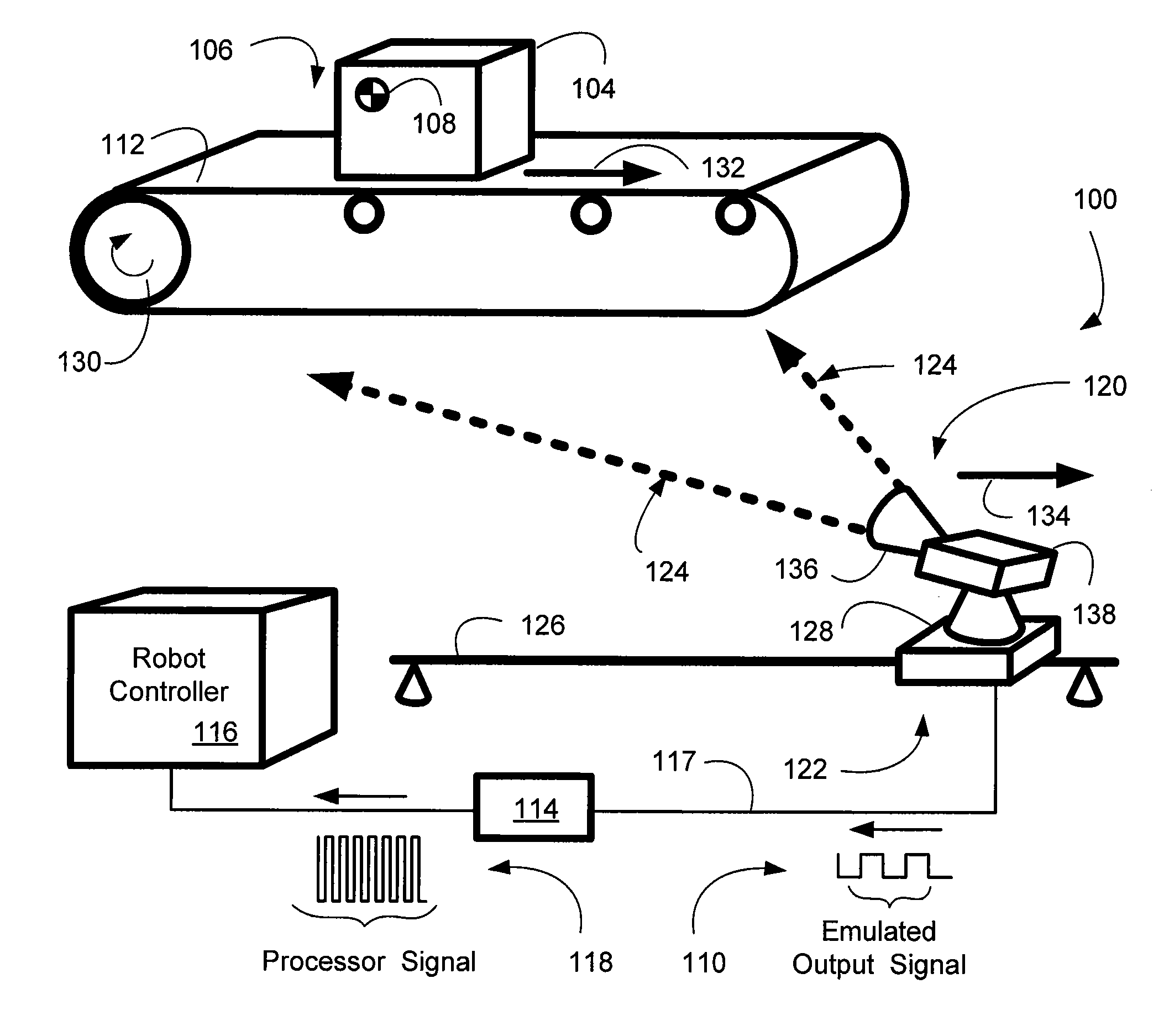
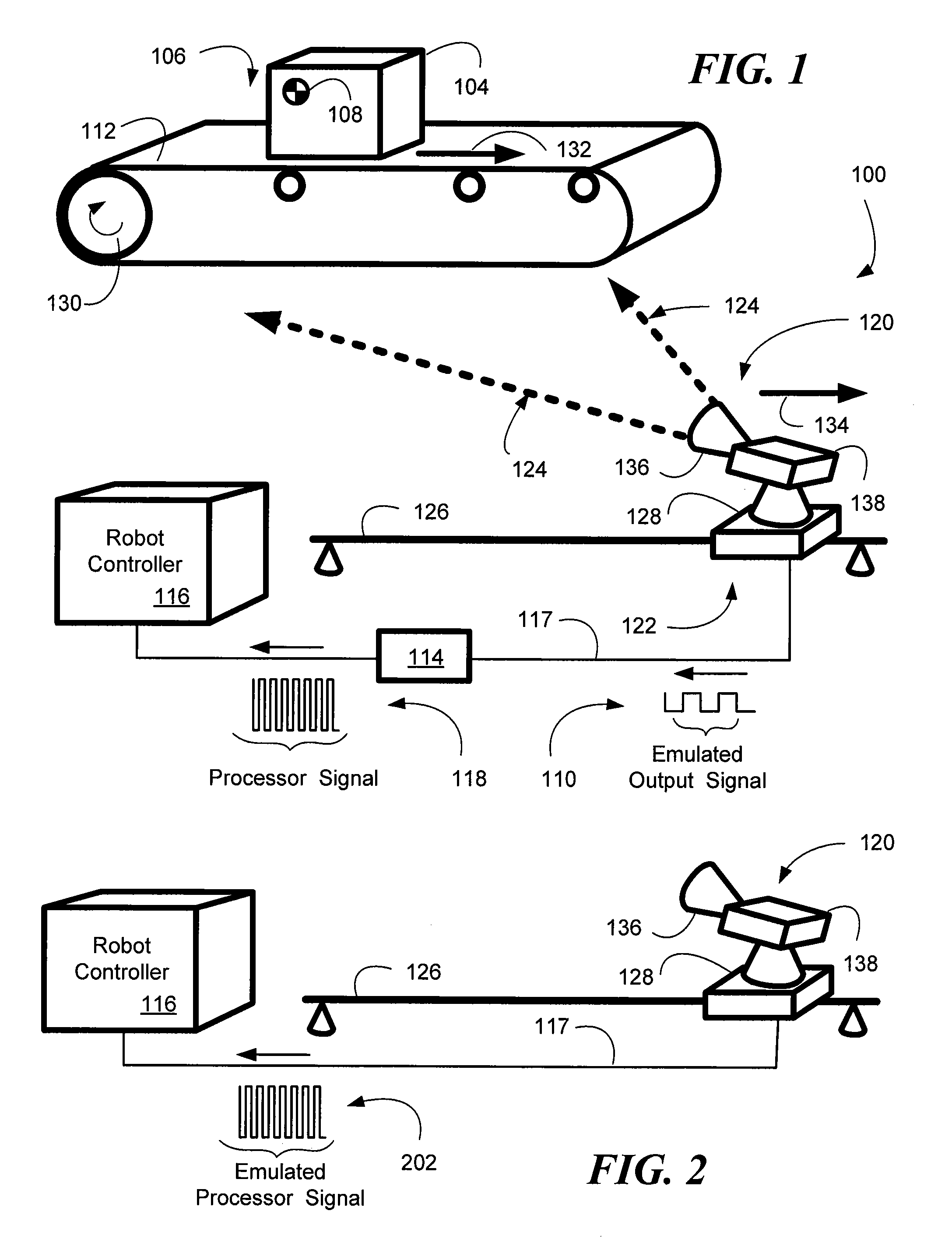
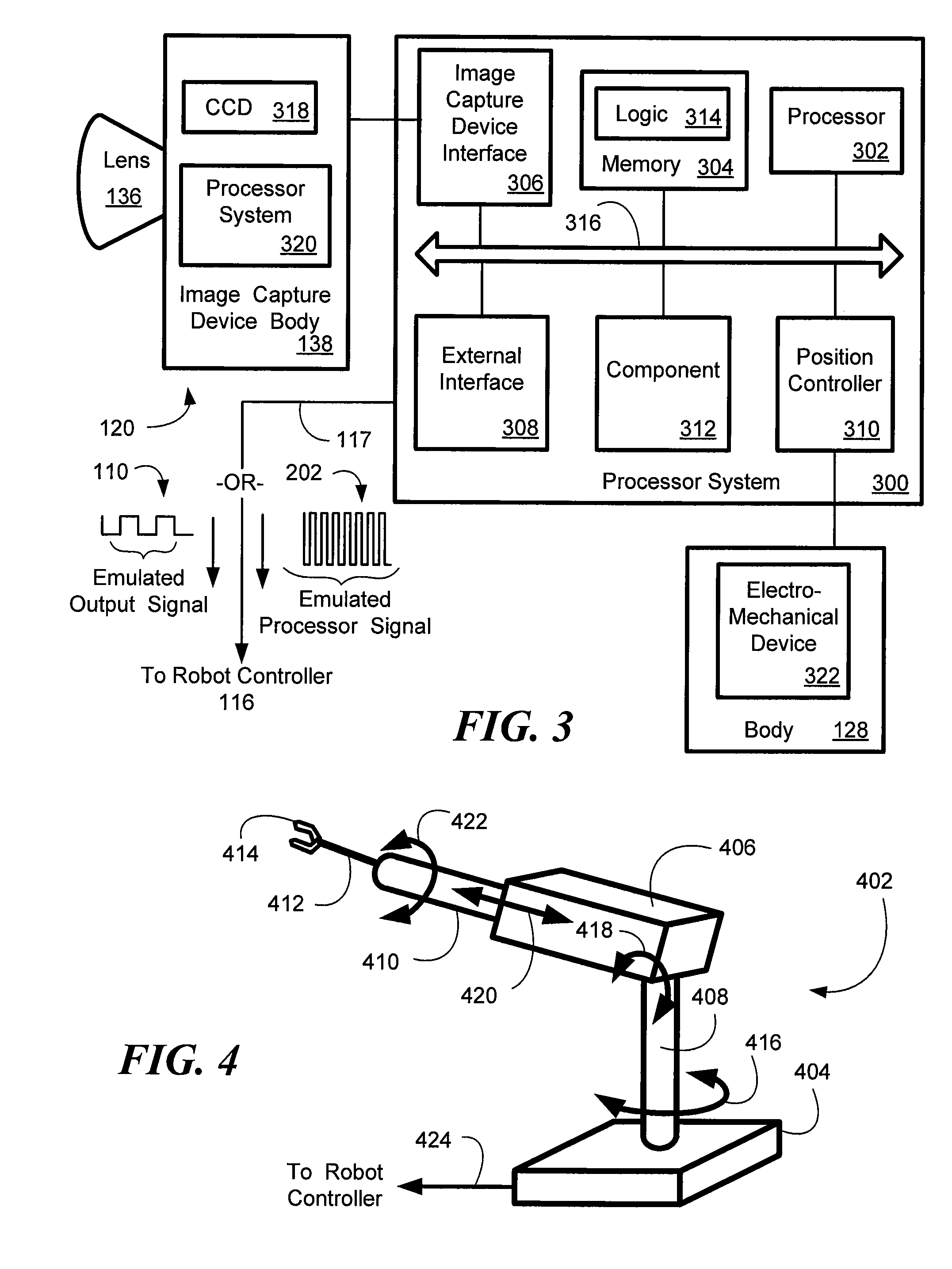
A machine-vision system, method and article is useful in the field of robotics. One embodiment produces signals that emulate the output of an encoder, based on captured images of an object, which may be in motion. One embodiment provides digital data directly to a robot controller without the use of an intermediary transceiver such as an encoder interface card. One embodiment predicts or determines the occurrence of an occlusion and moves at least one of a camera and/or the object accordingly.

Description

CROSS-REFERENCE TO RELATED APPLICATIONS [0001] This application claims benefit under 35 U.S.C. 119(e) to U.S. provisional patent application Ser. No. 60 / 719,765, filed Sep. 23, 2005.BACKGROUND OF THE INVENTION [0002] 1. Field of the Invention [0003] This disclosure generally relates to machine vision, and more particularly, to visual tracking systems using image capture devices. [0004] 2. Description of the Related Art [0005] Robotic systems have become increasingly important in a variety of manufacturing and device assembly processes. Robotic systems typically employ a mechanical device, commonly referred to as a manipulator, to move a working device or tool, called an end effector hereinafter, in proximity to a workpiece that is being operated upon. For example, the workpiece may be an automobile that is being assembled, and the end effector may be a bolt, screw or nut driving device used for attaching various parts to the automobile. [0006] In assembly line systems, the workpiece...

Claims


Application Information

Patent Timeline
IPC IPC(8): G06F7/00
CPCB25J9/1697G05B19/4182G05B2219/37189G06T7/2033G05B2219/40554G05B2219/40617G05B2219/40546G06T7/246Y02P90/02
Inventor HABIBI, BABAKCLARK, GEOFFREY C.
Owner BRAINTECH
Why Eureka
Try Eureka