Ferrite thin film, method of manufacturing the same and electromagnetic noise suppressor using the same

a technology of ferrite and thin film, which is applied in the field of spinel-type ferrite film, can solve the problems of large problem of application or adaptation to various kinds of electronic components, insufficient soft magnetic characteristics of ferrite films, and insufficient magnetic properties, etc., and achieves large magnetic permeability, improved form rate, and improved industrial productivity.

Inactive Publication Date: 2007-04-05
TOKIN CORP
View PDF9 Cites 12 Cited by
  • Summary
  • Abstract
  • Description
  • Claims
  • Application Information

AI Technical Summary

Benefits of technology

[0023] It is a first object of the present invention to provide, in ferrite films that are formed according to the ferrite plating process, with a formation rate improved and thereby industrial productivity increased, an extremely homogeneous ferrite film that has the uniaxial anisotropy and large magnetic permeability.
[0024] Furthermore, it is a second object of the present invention to provide, in ferrite films that are formed according to the ferrite plating process, with a formation rate improved and thereby industrial productivity increased, an extremely homogeneous ferrite film that does not have the magnetic directivity (isotropic).
[0028] Furthermore, it is a sixth object of the invention to provide a homogeneous ferrite film that is controlled in the crystal orientation and high in the magnetic permeability, and a method of manufacturing the ferrite films according to the ferrite plating process with a formation rate improved and thereby industrial productivity increased.

Problems solved by technology

However, the ferrite films according to the above-mentioned existing processes, in view of applying to an inductance element, impedance element, magnetic head, microwave element, magnetostrictive element and electromagnetic interference suppressor in a high frequency region, are insufficient in the soft magnetic characteristics.
Accordingly, a large problem existed as to applications or adaptations to various kinds of electronic components and so on.
Furthermore, in the case of a ferrite film that has the uniaxial anisotropy such as disclosed in the literature 8 being used in an inductance element, when for instance a spiral coil is used, a problem exists in that owing to the anisotropy of the magnetic film a portion where the magnetic flux density is locally lowered is generated inside of the element, as a result an inductance as a whole is lowered.
Furthermore, as mentioned above, various improvements have been proposed to improve a formation rate of a ferrite film; however, from an industrial productivity point of view, these are insufficient; accordingly, a large problem has been remained in the applications to various kinds of electronic components or in the adaptability thereto.
Accordingly, it is supposed that because fine ferrite grains that are secondarily formed other than on a solid surface disturb the crystal growth or Fe2+ is unevenly absorbed on a solid surface, a ferrite film that is an aggregation of homogeneous grains is obtained with difficulty.
In the case of the ferrite film particularly due to the ferrite plating process, as mentioned above, the ferrite film is formed through crystal growth from a starting point on the surface of the substrate; however, according to the existing processes, since fine ferrite grains secondarily formed other than on the surface of the substrate disturb the crystal growth or Fe2+ is unevenly absorbed on the surface of the substrate, the crystal orientation can be controlled with difficulty (for instance, as in the literature 10, when a ferrite film is formed on a surface of a substrate that is extremely small in the center line average roughness Ra, a homogeneous film can be obtained with difficulty, and the crystal orientation can be controlled with difficulty).
As a result, in spite of various improvements so far being proposed to improve the formation rate of the film, these improvements are insufficient from a viewpoint of the industrial productivity.
In addition to the above problem, there is a large technical problem in that when applying to the magnetic devices and adapting to various kinds of electronic components, high magnetic permeability cannot be obtained.

Method used


Image

  • Ferrite thin film, method of manufacturing the same and electromagnetic noise suppressor using the same
  • Ferrite thin film, method of manufacturing the same and electromagnetic noise suppressor using the same
  • Ferrite thin film, method of manufacturing the same and electromagnetic noise suppressor using the same

Examples


first embodiment

[0055] First, the present invention will be detailed.

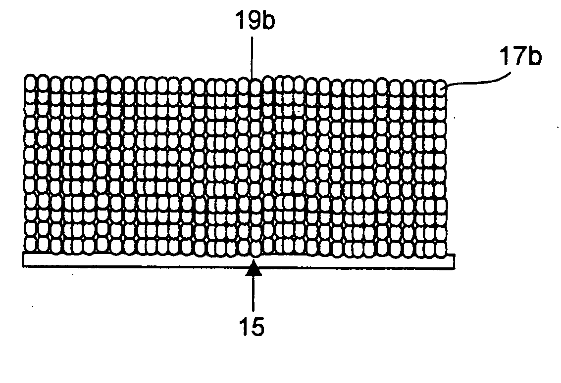
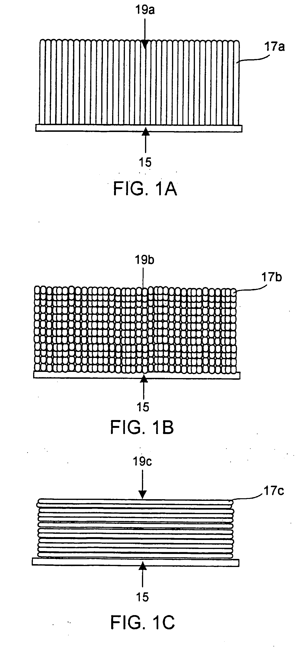
[0056] As shown in FIG. 1A, in a ferrite film 19a formed on a substrate 15, columnar grains 17a constituting the film 19a or constituting elements analogous to that are very uniformly distributed in the film 19a. Furthermore, in FIG. 1B, in a ferrite thin film 19b formed on the substrate 15, particulate grains 17b constituting the film 19b or constituting elements analogous to that are very uniformly distributed in the film 19b. Still furthermore, in FIG. 1C, in a ferrite thin film 19c formed on the substrate 15, layering grains 17c constituting the film 19c or constituting elements analogous to that are very uniformly distributed in the film 19c.

[0057] According to the invention, a ferrite thin film in which constituents (grains or constituents analogous to that) constituting a ferrite film are regularly arranged is obtained; anisotropic directions of the constituents having the uniaxial anisotropy are aligned in a particular d...

example 1

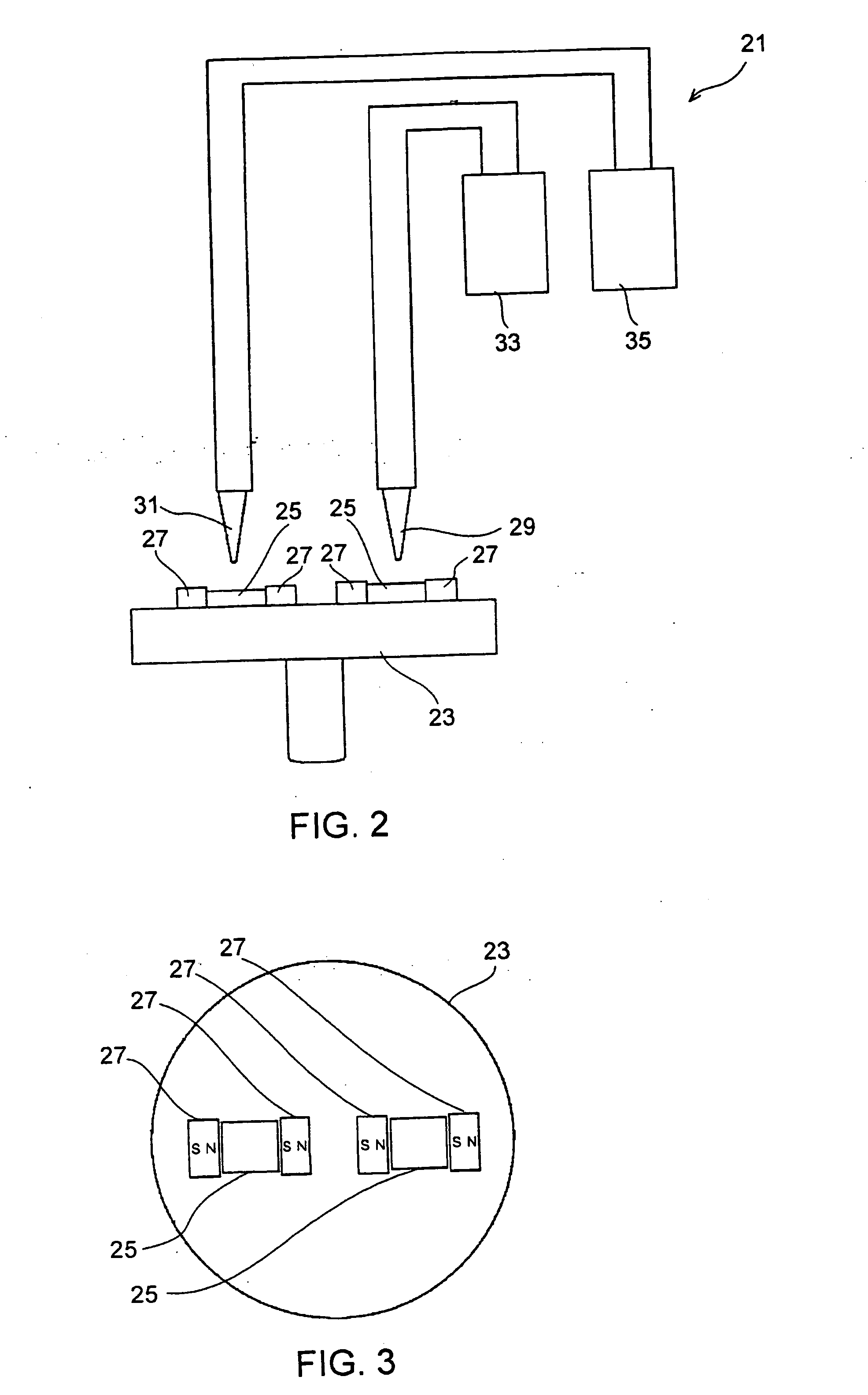
[0082] With reference to FIGS. 2 and 3, on the rotary table 23, as the substrate 25, glass plates rendered hydrophilic by plasma treatment are disposed and heated to 90 degree centigrade under a rotation at 150 rpm and supply of deoxygenated ion exchange water. At that time, it was confirmed that on a surface of the substrate 25, a magnetic field of substantially 50 Oe is applied in substantially parallel with a film plane. In the next place, in the apparatus, N2 gas was introduced and a deoxygenated atmosphere is established. Two kinds of reaction solutions were prepared. Into deoxygenated ion exchange water, FeCl2.4H2O, NiCl2. 6H2O, ZnCl2, and CoCl2. 6H2O, respectively, were dissolved by 3.3, 1.3, 0.03, and 0.1 g / L, and thereby a solution A was prepared. Into deoxygenated ion exchange water, FeCl2.4H2O, NiCl2.6H2O, and ZnCl2, respectively, were dissolved by 3.3, 1.3, and 0.03 g / L, and thereby a solution B was prepared. One of the reaction solutions A and B and an oxidizing solutio...

example 2

[0087] With reference to FIGS. 4 and 5, a glass plate rendered hydrophilic by plasma treating was disposed on tilting table 39 and was heated to 90 degree centigrade with deoxygenated ion exchange water supplying. Subsequently, N2 gas was introduced into apparatus and a deoxygenated atmosphere was established. Reaction solutions and an oxidizing solution similar to that in example 1 of the invention were prepared. After flow rates of the reaction solution and the oxidizing solution were adjusted to 30 ml / min, one of the reaction solutions A and B was supplied from a nozzle for 0.5 seconds followed by removing the reaction solution owing to the fluidity imparted to the reaction solution by the gravity, and the oxidizing solution was supplied from a nozzle for 0.5 seconds followed by removing the oxidizing solution owing to the fluidity imparted to the reaction solution by the gravity. With the above processes inclusive as one cycle, 2000 cycles were repeated. Thereafter, it was confi...


PUM

PropertyMeasurementUnit
roughnessaaaaaaaaaa
roughnessaaaaaaaaaa
weight ratioaaaaaaaaaa

Abstract

A ferrite film is formed by regularly arranging constituents such as magnetized grains or one analogous to that. In the ferrite film, the constituents have at least one of the uniaxial anisotropy and the multiaxial anisotropy. The ferrite film has the magnetic anisotropy or the magnetic isotropy. The ferrite film is formed by the use of the plating method in the presence of a magnetic field. Furthermore, an electromagnetic noise suppressor includes the ferrite film.

Description

[0001] This is a Divisional application of application Ser. No. 10 / 660,071 filed Sep. 11, 2003, now allowed.[0002] The present application claims priority to prior Japanese patent applications JP 2002-268932, JP-2002-26867 and JP 2002-269009, the disclosures of which are incorporated herein by reference. BACKGROUND OF THE INVENTION [0003] The present invention relates to a spinel type ferrite film high in the utility value in particular in high frequency magnetic devices such as, inductance elements, impedance elements, magnetic heads, microwave elements, magnetostrictive elements and electromagnetic interference suppressors that are used to suppress electromagnetic interference owing to the unnecessary electromagnetic waves in a high frequency region and a manufacturing method thereof. [0004] In a ferrite plating process, as mentioned in Japanese Unexamined Patent Publication No. S59-111929 (hereinafter referred to as “literature 1”), an aqueous solution containing at least ferrous...

Claims


Application Information

Patent Timeline
Patent Type & Authority Applications(United States)
IPC IPC(8): B32B15/00H01F1/00G11B5/706H01F10/20H01F41/24H05K1/02
CPCG11B5/70652H01F10/20H01F41/24Y10T428/32Y10T428/325Y10T428/12465H05K1/0233
Inventor KONDO, KOICHITAKAHATA, OKIKUNICHIBA, TATSUYAONO, HIROSHIYOSHIDA, SHIGEYOSHIABE, MASANORIYAMAGUCHI, MASAHIRO
Owner TOKIN CORP
Why Eureka
Try Eureka