Electroluminescent device

a technology of electroluminescent material and electrode, which is applied in the field of electroluminescent devices, can solve the problems of difficult coupling of excitons from electroluminescent materials into qds, limited stability of dye molecules, and difficulty in exciton transfer to quantum dots, so as to improve the power efficiency and performance of all devices, improve the power efficiency and performance of devices, and improve the effect of light emitting devices

Inactive Publication Date: 2007-04-05
KONINKLIJKE PHILIPS ELECTRONICS NV
View PDF7 Cites 59 Cited by
  • Summary
  • Abstract
  • Description
  • Claims
  • Application Information

AI Technical Summary

Benefits of technology

[0063] The invention may be applied to improve the power efficiency and performance of all devices based on an electroluminescent organic matrix with embedded QDs. The invention may thus lead to the use of such devices in a large number of applications where other light emitting devices are presently used. Also, it may lead to the use of such devices in areas into which the present efficiency of e

Problems solved by technology

However, because dye molecules often have limited stability, nano-sized semiconductor crystals referred to as quantum dots (QDs) have been proposed as a substitution for dyes in OLEDs and PolyLEDs.
One disadvantage of using QDs as compared with dyes is tha

Method used


Image

  • Electroluminescent device
  • Electroluminescent device
  • Electroluminescent device

Examples


Embodiment Construction

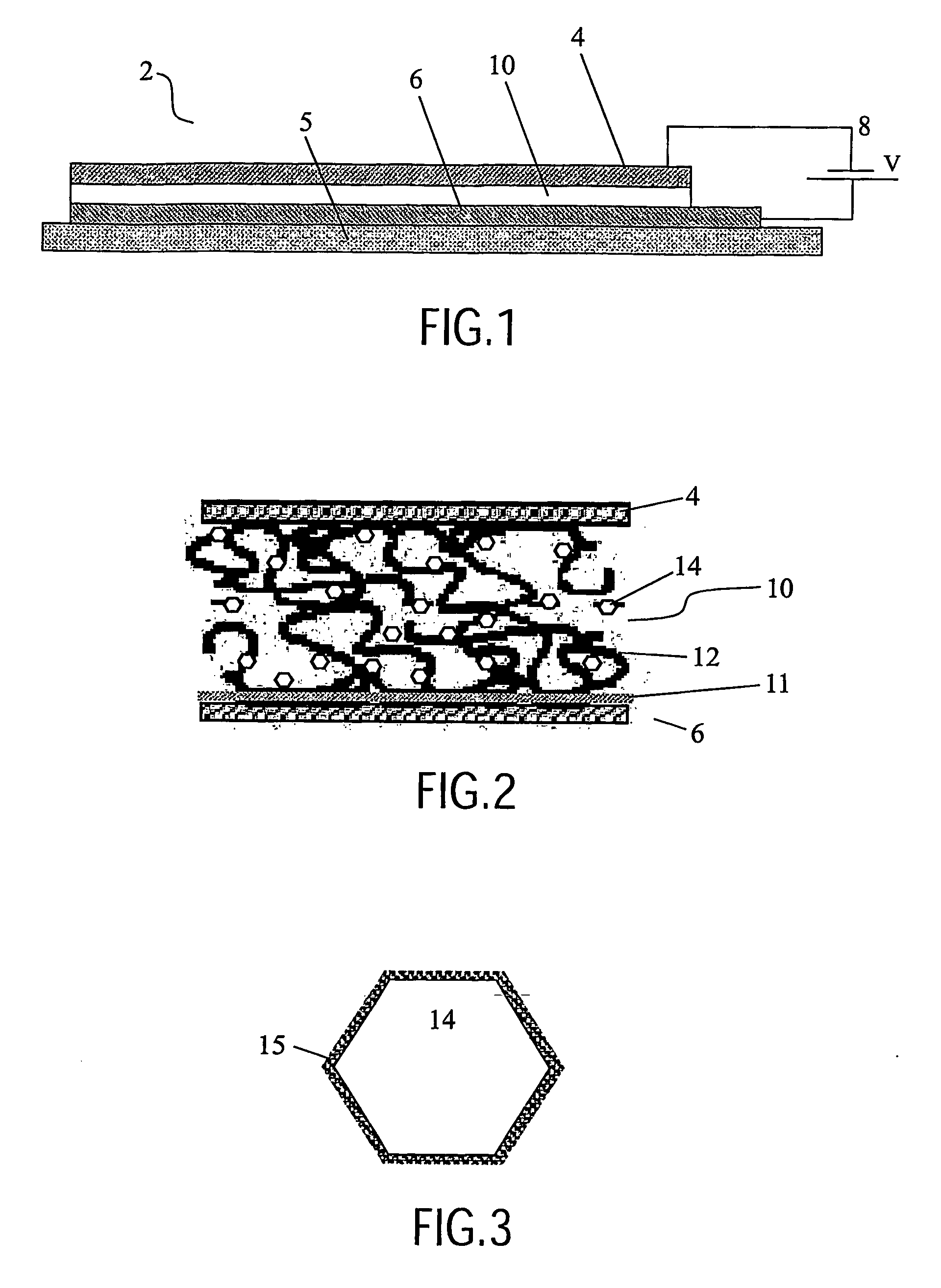
[0077] In a preferred embodiment shown in FIG. 1, the invention provides a light emitting device 2. The device comprises a cathode 4 and a transparent anode 6 on a transparent substrate 5 with a power supply 8 for creating an electrical field between these. Between the electrodes is a light emitting layer 10 consisting of a blend of electroluminescent organic molecules and QDs. In the described embodiments, the organic molecules are polymers.

[0078]FIG. 2 shows an illustration of an enlarged section of the device 2 of FIG. 1, the figure exaggerates the relative size. Here, the light emitting layer 10 is seen to consist of a matrix of polymers 12 with QDs 14 with transfer molecules distributed throughout the matrix. Also, a thin film planarising layer 11 is seen between the anode 6 and the light emitting layer 10.

[0079] In the following, a preferred method of fabrication of the light emitting device 2 of FIGS. 1 and 2 is described. When designing the device 2, the electrode work fun...


PUM


Abstract

The invention relates to a matrix of electroluminescent organic material having quantum dots embedded therein. Electrodes provide electrons and holes to the matrix forming excitons to be transferred to the quantum dots. The invention provides transfer molecules on the quantum dots facilitating the transfer of excitons from the electroluminescent organic material to the quantum dots, by first transferring them to the transfer molecules. The transfer molecules are chosen to make a transfer rate of excitons from the organic material to the transfer molecules larger than a decay rate of excitons in the organic material. More specifically, the organic matrix forms a light emitting layer in a light emitting device (LED). Also, the electroluminescent organic material is preferably an electroluminescent polymer.

Description

BACKGROUND OF THE INVENTION [0001] Organic electroluminescent devices are considered to be important in many applications ranging from lighting to full colour emissive displays. The basic structure is an emitting organic layer sandwiched between electrode layers and transport layers providing electrons and holes to the emitting layer. [0002] In organic electroluminescent devices, electrons injected into lowest unoccupied molecular orbital (LUMO) of the emitting organic layer are combined with the holes injected into the highest occupied molecular orbital (HOMO) creating hole-electron pairs (excitons) which recombine to emit light. It is therefore important to have balanced injection of holes and electrons, which recombine within the emitting layer. [0003] Organic light emitting materials, typically electroluminescent polymers, can be engineered to show both good electron as well as good hole transport. In addition, the HOMO and LUMO levels of electroluminescent polymers can be adjus...

Claims


Application Information

Patent Timeline
IPC IPC(8): G01N33/53B05D3/00H01L27/32H01L51/50
CPCB82Y10/00B82Y20/00H01L51/5016H01L27/3211H01L51/5012B82Y30/00H10K59/35H10K50/115H10K50/11H10K2101/10H05B33/14
Inventor HIKMET, RAFAT ATA MUSTAFAHOFSTRAAT, JOHANNES WILLEM
Owner KONINKLIJKE PHILIPS ELECTRONICS NV
Why Eureka
Try Eureka