
System and method for a chemical imaging threat assessor with a probe

a threat assessor and chemical imaging technology, applied in the field of systems and methods for chemical imaging threat assessors with probes, can solve the problems of inability to detect biothreat agents in all three media, inability to meet the desired ease of use and reliability, and inability to carry a single, portable instrument package, etc., to achieve the effect of facilitating sample analysis

Active Publication Date: 2007-04-12
CHEMIMAGE CORP
View PDF7 Cites 51 Cited by
  • Summary
  • Abstract
  • Description
  • Claims
  • Application Information

AI Technical Summary

Benefits of technology

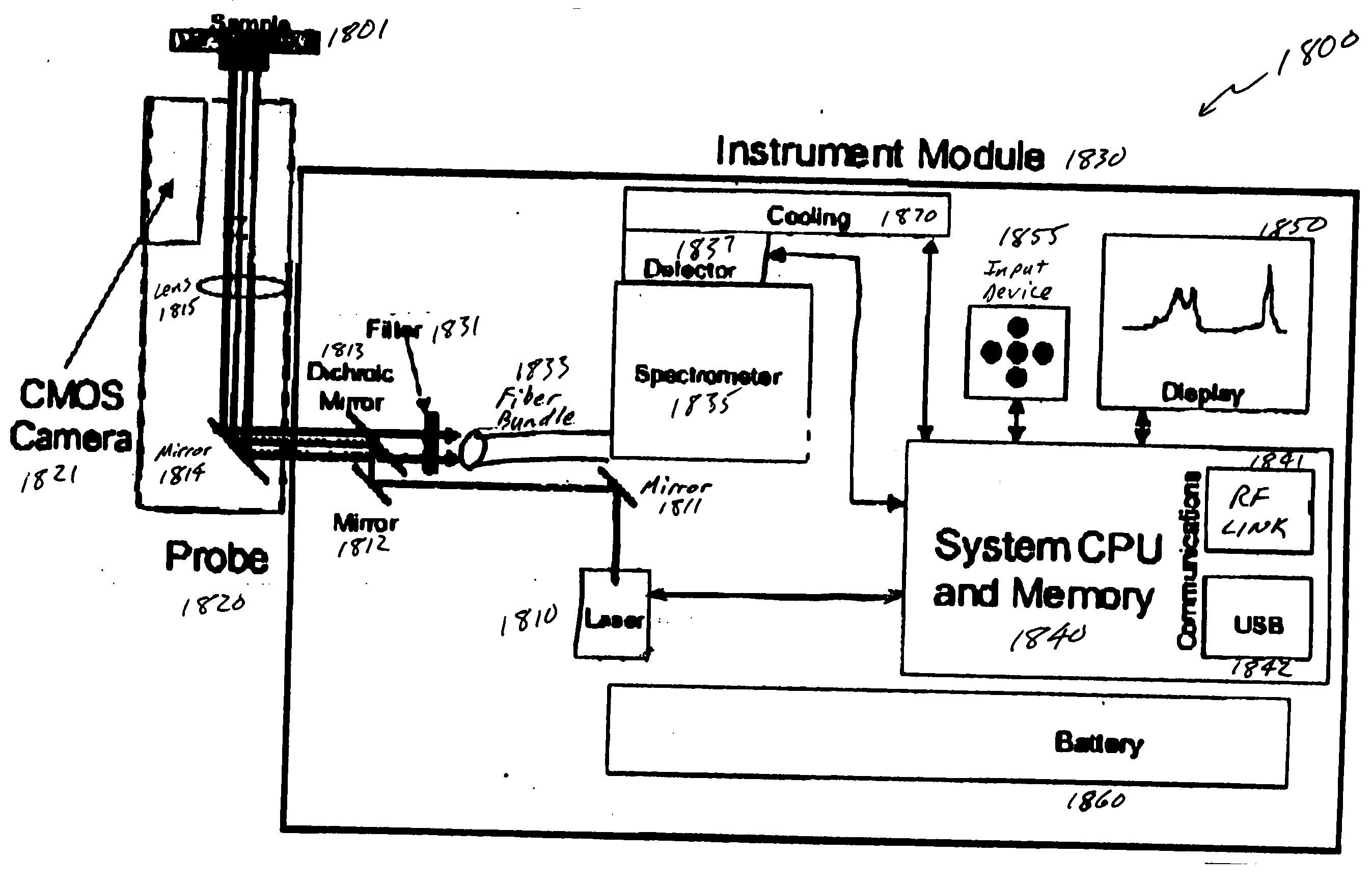
The patent is about a portable and handheld bioagent detector that uses advanced technology to identify multiple biological agents in the presence of near neighbors or clutter materials. The detector includes a probe with a complementary metal oxide semiconductor (CMOS) camera, which makes it easier to analyze samples in hard-to-reach locations. The patent also describes a portable system with a fiber array spectral translator (FAST) for obtaining a spatially accurate wavelength-resolved image of a sample for the detection of hazardous agents such as biothreat agents.

Problems solved by technology

Conventional systems are generally bulky and not portable.
However, there may be no single, portable, instrument package that can detect biothreat agents in all three media and meet the desired ease of use and reliability requirements.
However, specificity of detection is meaningless without enough sensitivity to detect a hazardous organism or toxin at or below a hazardous concentration.
Unfortunately, these hazardous levels have not been well characterized for many biothreat agents, making the development of detection limits and effective detectors somewhat difficult.
Current techniques for the detection of biological agents have the limitation of large size, high cost of consumables, limited ability to simultaneously detect more than one agent in a single test (i.e., limited multiplexing capability), long analysis times, limited sensitivity and susceptibility to false positive responses.

Method used


Image

  • System and method for a chemical imaging threat assessor with a probe
  • System and method for a chemical imaging threat assessor with a probe
  • System and method for a chemical imaging threat assessor with a probe

Examples


Embodiment Construction

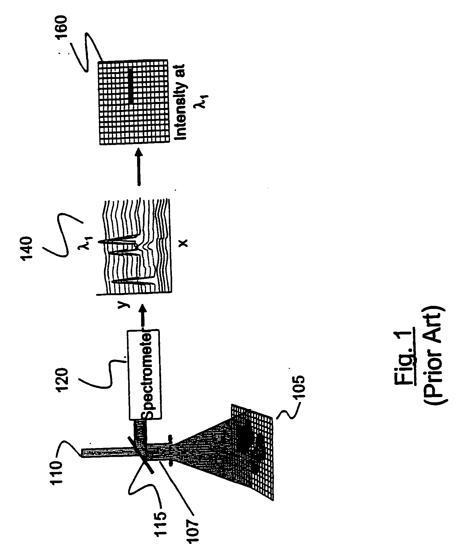
[0040]FIG. 1 is a schematic representation of one type of conventional line scan Raman imaging system, in particular a dispersive scan Raman imaging system employing a “pushbroom” scanning arrangement. A sample 105 is illuminated from a source 110, and light energy is reflectively back scattered from the sample and collected at optics 115. The image of the sample is accumulated from successive images at adjacent parallel lines in the image. The image of the sample is obtained for each such line and also at each of a plurality of specific wavelengths in the spectrum. Thus, a line or one-dimensional set of light amplitude values is sampled at a given location X1, Y1, . . . Yn. The light is filtered for specific wavelengths using a spectrometer 120 that functions as a variable wavelength bandpass filter. By advancing from line to line in a “pushbroom” sequence, the successive amplitude values shown graphically at plot 140 are converted to intensity pixel values in an array 160 for a gi...


PUM

PropertyMeasurementUnit
wavelengthaaaaaaaaaa

Abstract

The disclosure relates to a portable and / or handheld bioagent detector and methodology described herein that is based in part on advanced Raman Chemical Imaging (“RCI”) technology. According to one embodiment of the present disclosure, the detection system may include a fiber array spectral translator (“FAST”) and may also include a probe which may include a complementary metal oxide semiconductor (CMOS) camera. The probe alleviates the need to place the main instrument close to an unconfined release of a potentially hazardous material and facilitates analysis of a sample that is situated in a hard-to-reach location while minimizing contamination of the detector and operator.

Description

RELATED APPLICATIONS [0001] The present application hereby incorporates by reference in its entirety and claims priority benefit from U.S. Provisional Patent Application Ser. No. 60 / 724,576 filed 7 Oct. 2005.BACKGROUND [0002] Spectroscopic imaging combines digital imaging and molecular spectroscopy techniques, which can include Raman scattering, fluorescence, photoluminescence, ultraviolet, visible and infrared absorption spectroscopes. When applied to the chemical analysis of materials, spectroscopic imaging is commonly referred to as chemical imaging. Instruments for performing spectroscopic (i.e. chemical) imaging typically comprise image gathering optics, focal plane array imaging detectors and imaging spectrometers. [0003] In general, the sample size determines the choice of image gathering optic. For example, a microscope is typically employed for the analysis of sub micron to millimeter spatial dimension samples. For larger objects, in the range of millimeter to meter dimensi...

Claims


Application Information

Patent Timeline
Patent Type & Authority Applications(United States)
IPC IPC(8): G01J3/44G01N21/65
CPCG01J3/02G01J3/0205G01J3/0218G01J3/0224G01J3/0227G01J3/0256G01J3/0264G01J3/027G01J3/0272G01J3/0283G01J3/0286G01J3/0289G01J3/0291G01J3/10G01J3/26G01J3/2803G01J3/2823G01J3/44G01J3/4406G01J3/447G01N21/65G01N2021/656G01N2201/0846
Inventor TREADO, PATRICK J.VOIGT, THOMAS C.HUTCHISON, WESLEY H.
Owner CHEMIMAGE CORP
Learn More