Exposure method
a technology of exposure and exposure pattern, applied in the field of exposure, can solve the problems of difficult image, insufficient analysis of optimal exposure condition to checker pattern, and the appearance of improvement limits, and achieve the effect of improving imaging characteristics and sufficient do
- Summary
- Abstract
- Description
- Claims
- Application Information
AI Technical Summary
Benefits of technology
Problems solved by technology
Method used
Image
Examples
first embodiment
[First Embodiment]
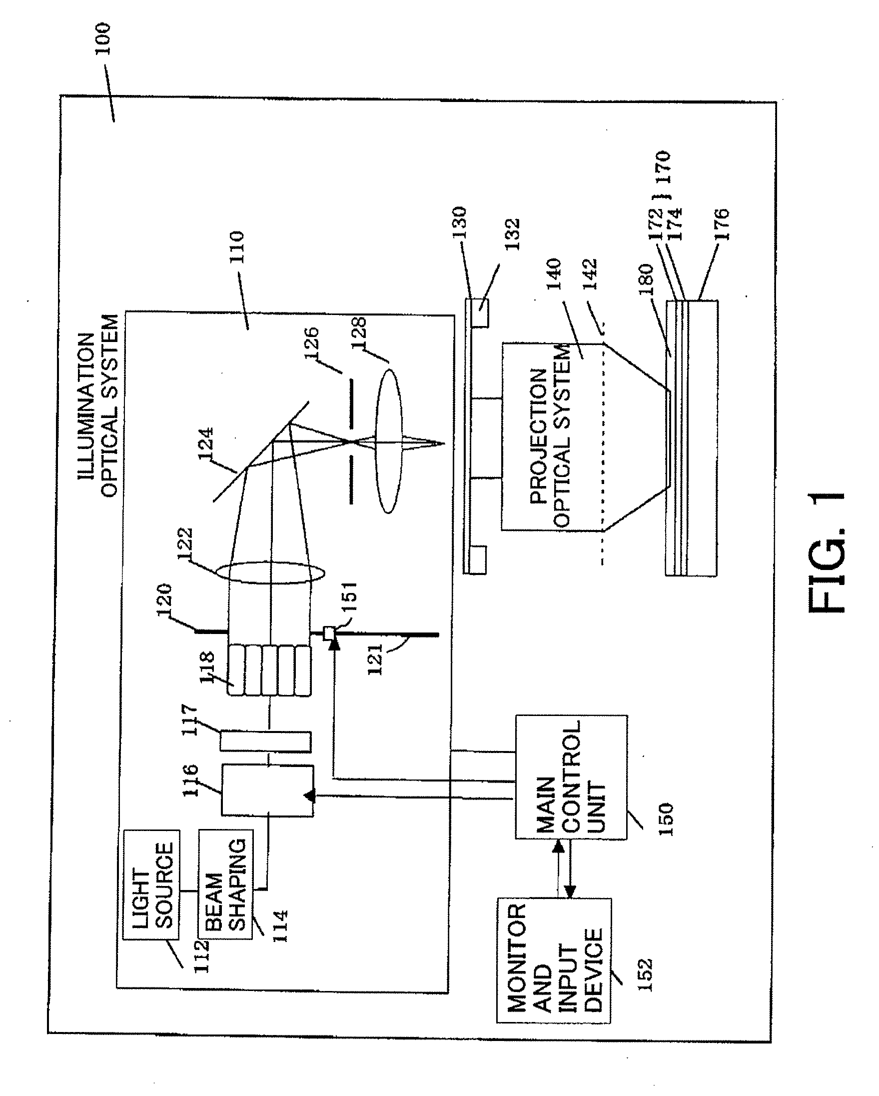
[0169] This embodiment uses an immersion exposure apparatus that uses an ArF excimer laser and an NA of 1.35 to wholly image the pattern MP20. The mask is an attenuated-PSM. The water's refractive index is about 1.44. An analysis result will be given of the imaging characteristic of the quadrupole illumination using the contrast and the CD DOF as evaluation criteria. The contrast is defined from the maximum and minimum values of the light intensity on the X section. The contrast on the X and Y sections can be similarly defined in the pattern MP21, whereas a definition of the contrast on the Y section cannot be similar to that on the X section in the pattern MP22, because the contact holes are arranged every other array.
[0170] The exposure process is unavoidable with the exposure dose error and the focus setting error, but the contact holes should be produced on the image plane within the actual permissible range. It is said that the contrast of 40% or higher is ne...
second embodiment
[Second Embodiment]
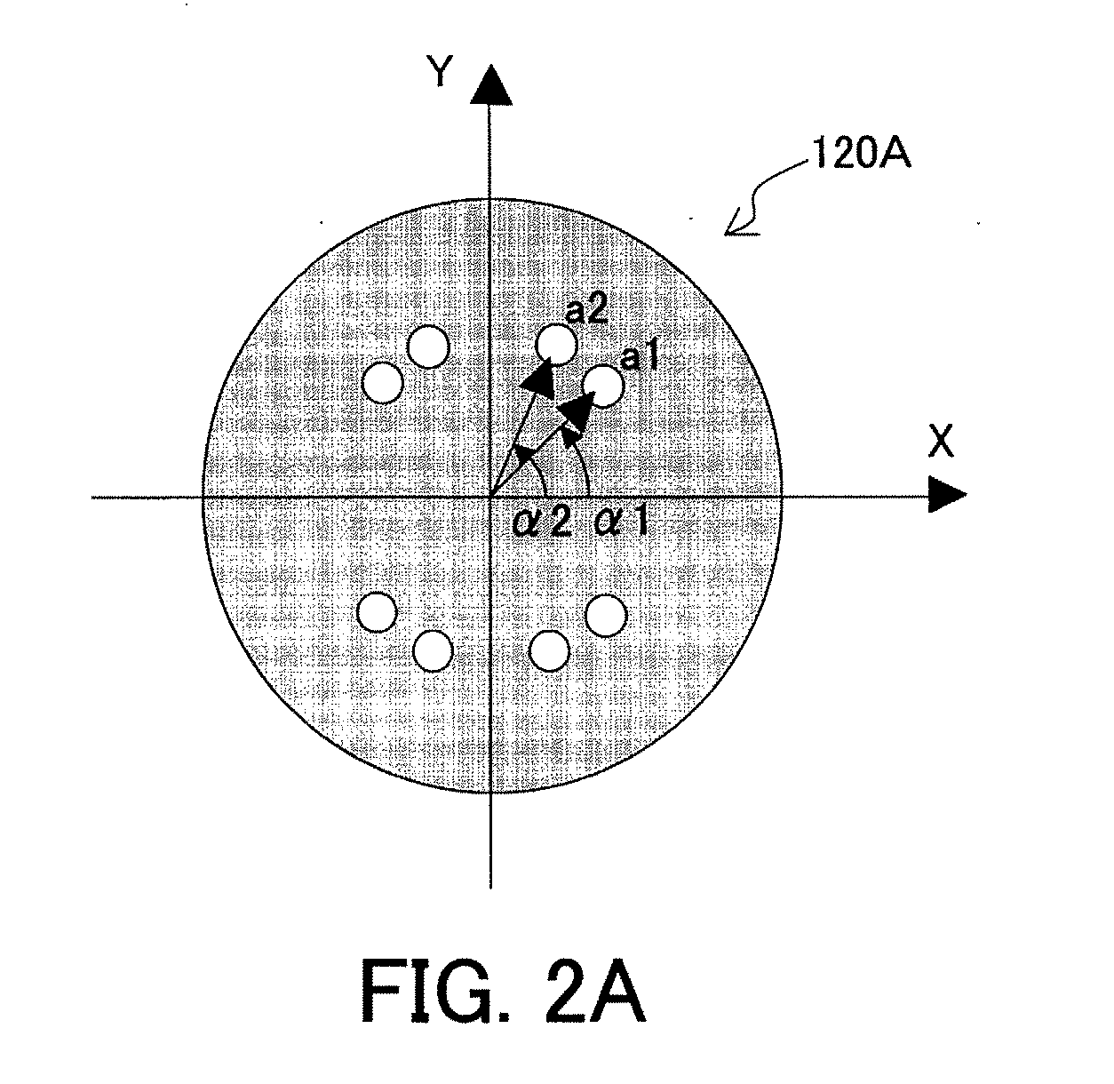
[0180] A hexapole illumination is used to image a hybrid pattern of the patterns MP21 and MP22 of Px=Py=P or having the same pitch in the longitudinal direction and the lateral direction. The mask is an attenuated-PSM. The contrast and DOF are shown when the immersion exposure apparatus similar to the first embodiment is used to image the pattern while changing the contact hole pitch. First, the way of variation of the contrast depending upon the polarization direction is studied. The effective source is the hexapole illumination shown in FIGS. 17A and 17B with σ=0.70 and σr=0.10. The radial polarization, the tangential polarization, and an unpolarization are compared.
[0181]FIG. 20A shows a contrast on the X section of the pattern MP21. FIG. 20B shows a contrast on the X section of the pattern MP22. The horizontal axis denotes the half pitch of the contact hole (nm), and the vertical axis denotes the contrast peak. It is understood from FIGS. 20A and 20B that the...
third embodiment
[Third Embodiment]
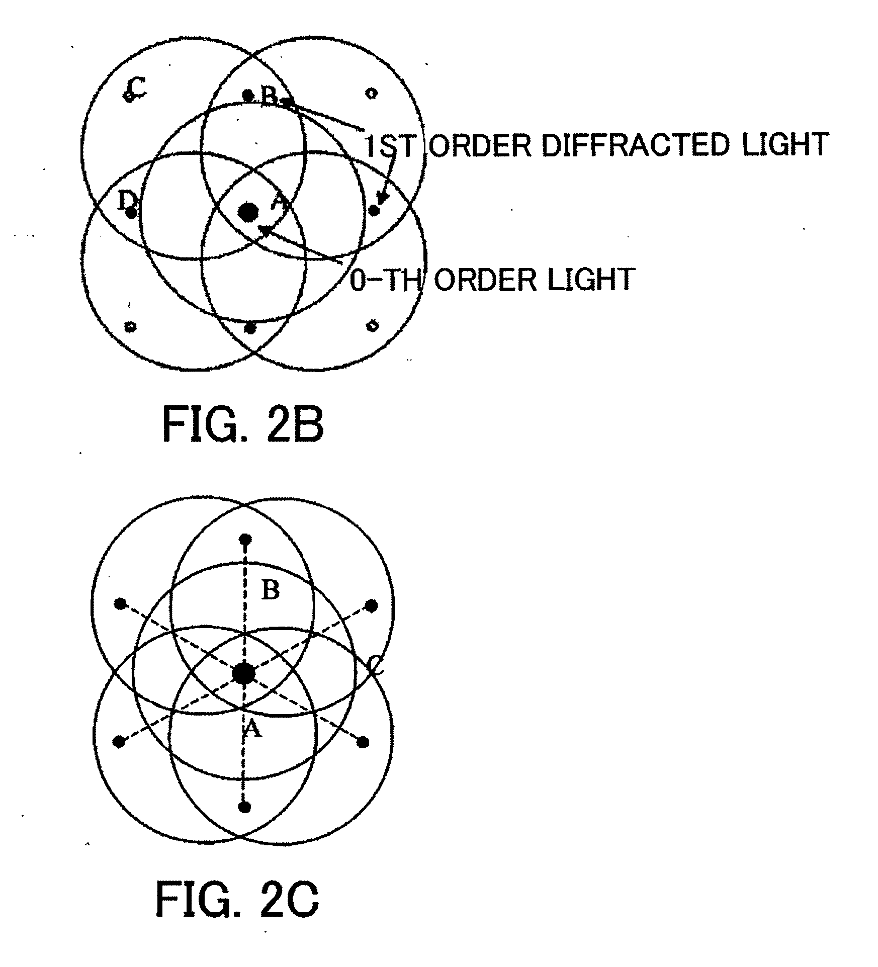
[0184] A description will now be given of the illumination condition of the hybrid pattern of the matrix pattern MP21 shown in FIG. 24 and the checker pattern MP22 which hybrid pattern is made by inserting an auxiliary pattern into the pattern shown in FIG. 23. The mask is an attenuated-PSM, and a size of the contact hole is 60 nm. Px=Py=120 nm, and the auxiliary pattern has a width of 60×0.8=48 (nm). An immersion exposure apparatus having an ArF (193 nm) and an NA of 1.35 is used for exposure with the above exposure condition. When half pitches Px / 2=Py / 2=60 nm in the X and Y directions are k1-converted, k1=0.42 or Pxo / 2=Pyo / 2=0.42 and Pxo / Pyo=d=1 are satisfied.
[0185] As described above, the optimal exposure condition for the illumination condition of the patterns shown in FIGS. 24A and 24B is derived from Equation 64 as follows:
α1=tan−1(d)=45(deg) [EQUATION 74]
a1=1 / (1.424·0.42·2)=0.84 [EQUATION 75]
[0186] The optimal exposure condition of the pattern shown in FI...
PUM
| Property | Measurement | Unit |
|---|---|---|
| wavelength | aaaaa | aaaaa |
| wavelength | aaaaa | aaaaa |
| wavelength | aaaaa | aaaaa |
Abstract
Description
Claims
Application Information
 - R&D
- Intellectual Property
- Life Sciences
- Materials
- Tech Scout
- Unparalleled Data Quality
- Higher Quality Content
- 60% Fewer Hallucinations
Browse by: Latest US Patents, China's latest patents, Technical Efficacy Thesaurus, Application Domain, Technology Topic, Popular Technical Reports.
© 2025 PatSnap. All rights reserved.Legal|Privacy policy|Modern Slavery Act Transparency Statement|Sitemap|About US| Contact US: help@patsnap.com


