Electrostatic fluid treatment apparatus and method

a technology of electrostatic fluid and treatment apparatus, which is applied in the direction of peptides, liquid/fluent solid measurement, and the nature of treatment water, etc., can solve the problems of reducing fluid flow, loss of heat transfer capability, and adverse effects on the operation of the system, so as to reduce installation costs, increase efficiency, and reduce fluid flow. , the effect of good toughness and durability

Inactive Publication Date: 2007-05-03
FLUID TREATMENT SOLUTIONS
View PDF3 Cites 7 Cited by
  • Summary
  • Abstract
  • Description
  • Claims
  • Application Information

AI Technical Summary

Benefits of technology

[0015] A principal object of the instant invention is to provide an electrostatic charge generator for use in high volume, large-scale, fluid treatment systems. Another object of the instant invention is to provide a high voltage (about 30,000 volts or higher) electrode that has good toughness, strength and durability. Yet another object of the instant invention is to provide a high voltage electrode that will lower installation costs, operational costs and also increase efficiency. Another object of the instant invention is to provide an electrode composition that allows for various physical, chemical and electrical characteristics to improve overall performance, reliability and design flexibility.

Problems solved by technology

As the minerals in solution are precipitated they will tend to deposit on the higher temperature surfaces within the recirculating system causing adverse effects on the operation of the system.
Deposited scale results in such operational disadvantages as reduced fluid flow, loss of heat transfer capability, decreased safety due to chemical treatments, increased corrosion and enhanced bio fouling.
Additionally, the thinner the layer of PTFE, the greater the potential vulnerability to puncture damage during installation and operation.
It has been found that electrodes using PTFE as an insulation layer are not suitable for efficient and dependable operation at voltages higher than approximately 10,000 volts, beyond which they quickly experience breakdowns.
While this was an improvement over the lower voltage electrodes of the prior art, the use of a more brittle vitreous ceramic insulation layer presents several disadvantages during installation and operation of the electrode.
A sufficient impact on the exterior of the electrode of Pitts, as is quite common during installation, will result in damage to the insulation layer that will render the electrode useless.
Additionally, breakage of the electrode during operation can dislodge pieces of the ceramic material, blocking fluid flow and causing damage to pumps, valves, heat exchangers, or other components of a fluid system.
Additionally, the tubular shape limits the total available active surface area and hence the size of the electric field that can be applied to the fluid.
Use of a direct insert installation requires significant downtime of the fluid system while the electrode is installed.
Such an installation can take up to eight hours for a single electrode.
Such long down times are very disruptive and often requires that installation be made during cooler months or during period in which the system can be shut down.
Furthermore, the use of a direct insert electrode limits the overall size of the electrode that can be used due to the limited dimensions of the pipe and flow restrictions created by the insertion of the electrode.
Nevertheless, it is usually still necessary to cut a hole in the holding tank and insert a socket for supporting the electrode or else utilize a preexisting socket within the holding tank.
This is because the electrodes of the prior art often lack sufficient water-excluding properties to be entirely submerged in the fluid.
Although installation of an electrode within a grounded holding tank does increase the volume of water that is subjected to the electric field, it does not provide adequate fluid contact time nor sufficient electric field intensity due to large separation distances (i.e., size of tank) to be effective at reducing scale formation.
The use of a separate ground electrode does increase the effectiveness of the electric field; however, the prior art installations do not attempt to increase the dwell time at a single location within the holding tank.

Method used


Image

  • Electrostatic fluid treatment apparatus and method
  • Electrostatic fluid treatment apparatus and method
  • Electrostatic fluid treatment apparatus and method

Examples


Embodiment Construction

[0040] Preferred embodiments of the present invention are hereinafter described with reference to the accompanying drawings.

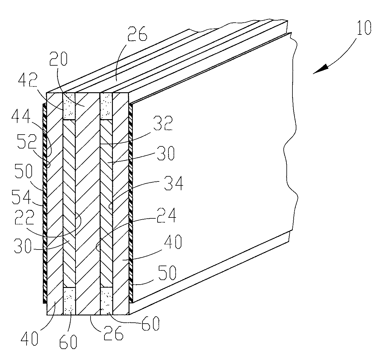
[0041] Referring to FIG. 12 a perspective view of a preferred embodiment of the multi-layered electrode of the instant invention in the form of a plate. The plate electrode shown in the instant invention has been designed to have a generally flat shape. Nevertheless other shapes, such as a curved shape can be utilized to provide a more uniform electric field or to optimize fluid flow characteristics (i.e. increase dwell time and / or decrease back-pressure) of the plate for use in numerous possible applications.

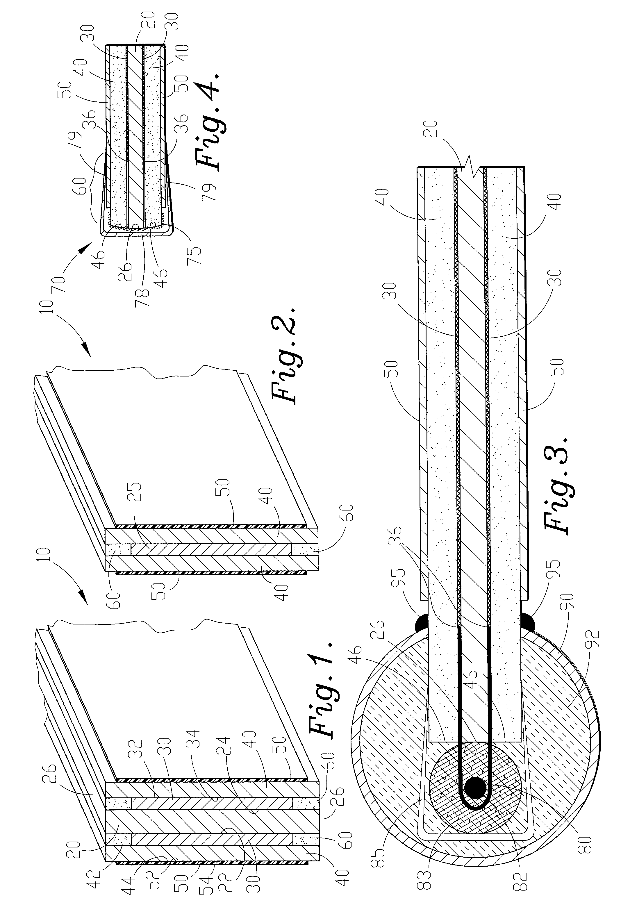
[0042]FIGS. 1 & 2 show two alternative embodiments of the construction of the flat plate electrode shown in FIG. 12. In FIGS. 1 & 2, portions of isolation frame 70 (discussed below with respect to FIG. 4) have been excluded for clarity. FIGS. 1 & 2 are cross-sectional views of the flat plate electrode of FIG. 12 taken along cross-section line 1-1. In FIG...


PUM

PropertyMeasurementUnit
voltageaaaaaaaaaa
voltageaaaaaaaaaa
voltagesaaaaaaaaaa

Abstract

A high voltage electrode and method of construction is provided including a multi-layered composition to optimize dielectric strength, dielectric constant, structural strength and durability. The high voltage electrode can be utilized as a submergible drop-in unit for easy installation within a fluid holding tank such as a water cooling tower. The submergible generator includes a channel that houses a charged electrode, and functions as a ground electrode to the charged electrode, and also functions as a fluid diverter.

Description

RELATED APPLICATIONS [0001] The present patent application is a division and claims priority benefit of an earlier-filed non-provisional patent application of the same title, Ser. No. 10 / 337,465, filed Jan. 7, 2003. The identified earlier-filed patent application is hereby incorporated by reference herein.FIELD OF THE INVENTION [0002] The present invention relates to the electrostatic treatment of fluids to enhance chemical reactions. More specifically, the present invention relates to improvements in electrostatic field generator apparatuses and electric fields in a fluid to increase the formation rate of small colloidal particles (crystalline). BACKGROUND OF THE INVENTION [0003] Electrostatic treatment is used in aqueous and non-aqueous fluid such as process water treatment, petroleum based fluids and paint solids / water (detackification) mixtures. Electrostatic treatment is particularly useful for removal and prevention of scale deposits in water recirculating heat exchange system...

Claims


Application Information

Patent Timeline
Patent Type & Authority Applications(United States)
IPC IPC(8): B03C5/02C02F1/469B04B5/10C02F1/00C02F1/461C02F1/48
CPCC02F1/006C02F1/46109C02F1/48C02F2001/46138Y10T29/49002C02F2103/023C02F2301/043C02F2303/22F28F25/00C02F2001/46152
Inventor MCLACHLAN, DAVIDBRIDGE, WILLIAMWILSON, ALLEN
Owner FLUID TREATMENT SOLUTIONS
Why Eureka
Try Eureka