Heat spreaders with vias

a heat spreader and via technology, applied in the direction of electrical apparatus construction details, light and heating apparatuses, printed circuit aspects, etc., can solve the problems of reducing the heat transfer rate of graphite materials with a high in-plane thermal conductivity, affecting the heat transfer rate of graphite materials, etc., to achieve the effect of improving heat transfer and low cos

Inactive Publication Date: 2007-05-10
NEOGRAF SOLUTIONS LLC
View PDF38 Cites 57 Cited by
  • Summary
  • Abstract
  • Description
  • Claims
  • Application Information

AI Technical Summary

Benefits of technology

[0029] And another object of the present invention is the provision of a flanged via having a flange engaging one of the major surfaces of the graphite heat spreader for improved heat transfer between the via and the graphite heat spreader.
[0030] And another object of the present invention is the provision of a low cost method of manufacturing heat spreaders with vias, utilizing inexpensive push on nuts.

Problems solved by technology

However, graphite materials with a high in-plane thermal conductivity have relatively lower through-thickness thermal conductivity.
This low through-thickness thermal conductivity impedes the flow through the thickness of the graphite and does not allow for maximum heat transfer through the spreader.
Such components can generate substantial amounts of heat that must be dissipated for them to operate reliably and to their intended performance levels.
As a result of these heat generating components, the amount of heat that printed circuit boards must help dissipate can be significant.
The use of thermally conductive particles can be expensive, however, and the subsequent layer must be thick enough to ensure it is pin-hole free, adding to thermal resistance in the design.
Additional limitations of this approach arise from the lack of flexibility to fabricate bent or non-planar circuit structures, and the fact that the dielectric material covers the entire surface of the heat spreader layer.
The use of anodization as the dielectric layer attempts to overcome some of these issues, but forces the use of aluminum as its heat spreader layer, since copper cannot be anodized.
Since the thermal conductivity of aluminum is significantly less than that of copper, this can be a thermal disadvantage.
All of the foregoing approaches, however, can suffer soldering difficulties, since the same heat dissipation properties that are useful during the operation of the printed circuit board and components, inhibit an assembly process that requires point sources of heat for soldering (such as hot bar bonding, for example).
Moreover, traditional heat spreading materials like copper or aluminum also add significant weight to the board, which is undesirable, and the coefficient of thermal expansion (CTE) of these materials may not closely match that of the glass fiber laminate, leading to physical stress on the printed circuit board with the application of heat and, potentially, delamination or cracking.
Additionally, since the heat spreader layer on these boards is comprised of an isotropic, thin (relative to its length and width) metal material, heat tends to flow through the thickness of the heat spreader readily, and resulting hot-spots can occur in the location directly opposite the heat source.
Another type of circuit assembly, referred to in the industry as a “flex circuit,” provides similar heat management problems.
While very thin, the dielectric layer in flex circuits still adds appreciably to the thermal resistance in a given design, and suffers from some of the same issues observed in printed circuit boards.
The use of thermal vias is still limited to electrically isolating applications as described previously.
And as is apparent, the use of rigid metallic layers, such as of copper or aluminum, does not allow one to take advantage of the flexibility of flex circuits, where such a characteristic is important in an end-use application.
In addition, graphite has an in-plane CTE of essentially zero, and lower stiffness than copper or aluminum, thus reducing thermal stresses at the graphite-dielectric bond.
While sheets of compressed particles of exfoliated graphite can even have the flexibility for use with flex circuits, the addition of a graphite-based heat spreader layer cannot counter all of the disadvantages arising from the location of a heat spreader such that one or more layers of dielectric material separate the heat spreader from the heat-generating components, with the reduced heat transfer from the components to the heat spreader layer.
However, nothing in the Krassowski and Chen disclosure describes conducting heat from a heat source through layers of a relatively non-conductive material like a dielectric layer of a circuit assembly.

Method used


Image

  • Heat spreaders with vias
  • Heat spreaders with vias
  • Heat spreaders with vias

Examples


Embodiment Construction

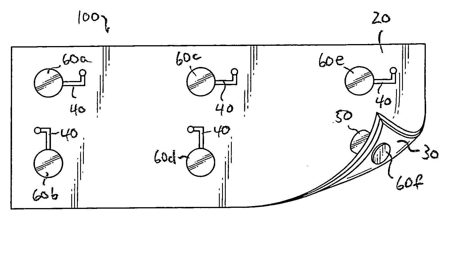
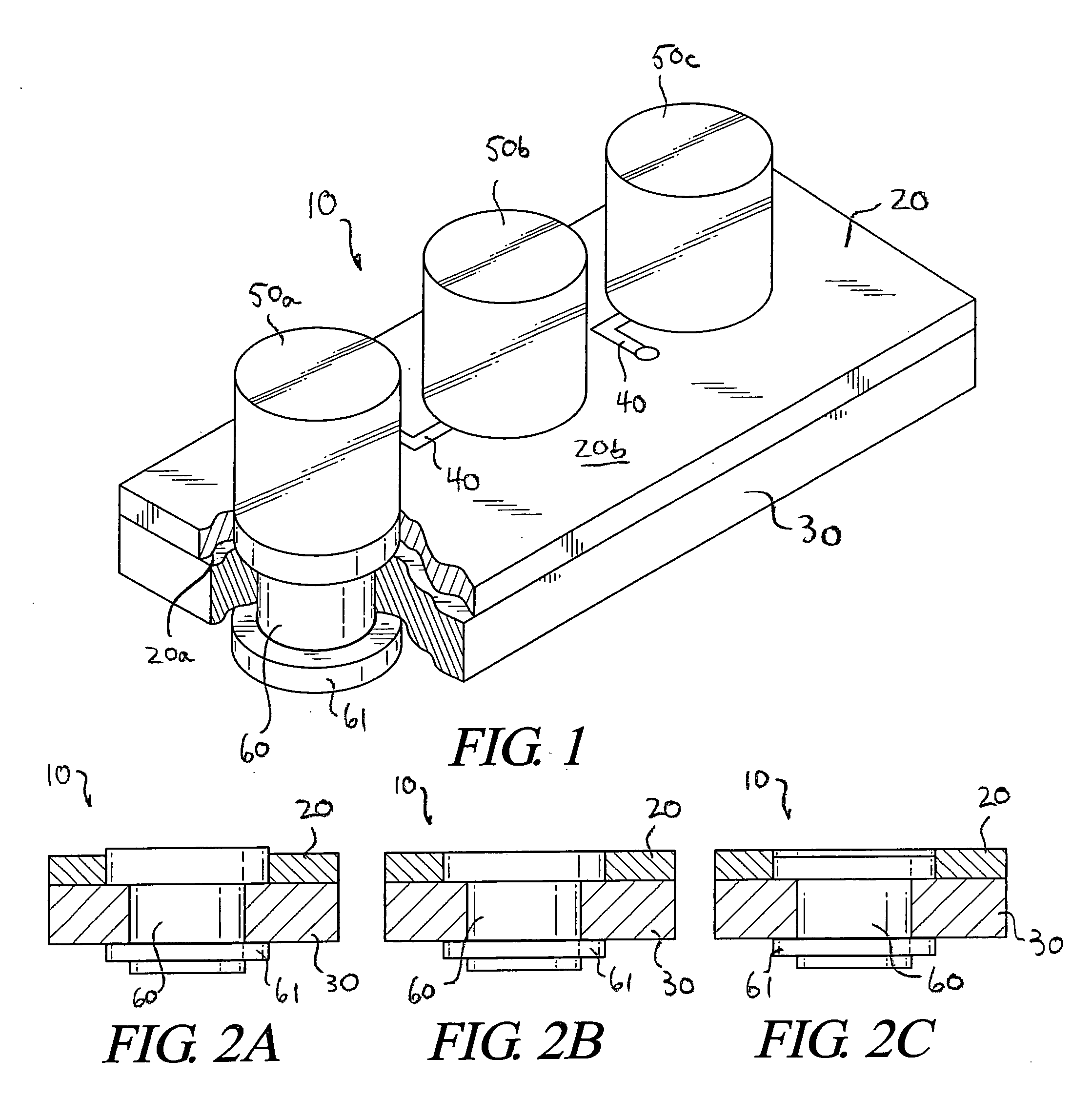
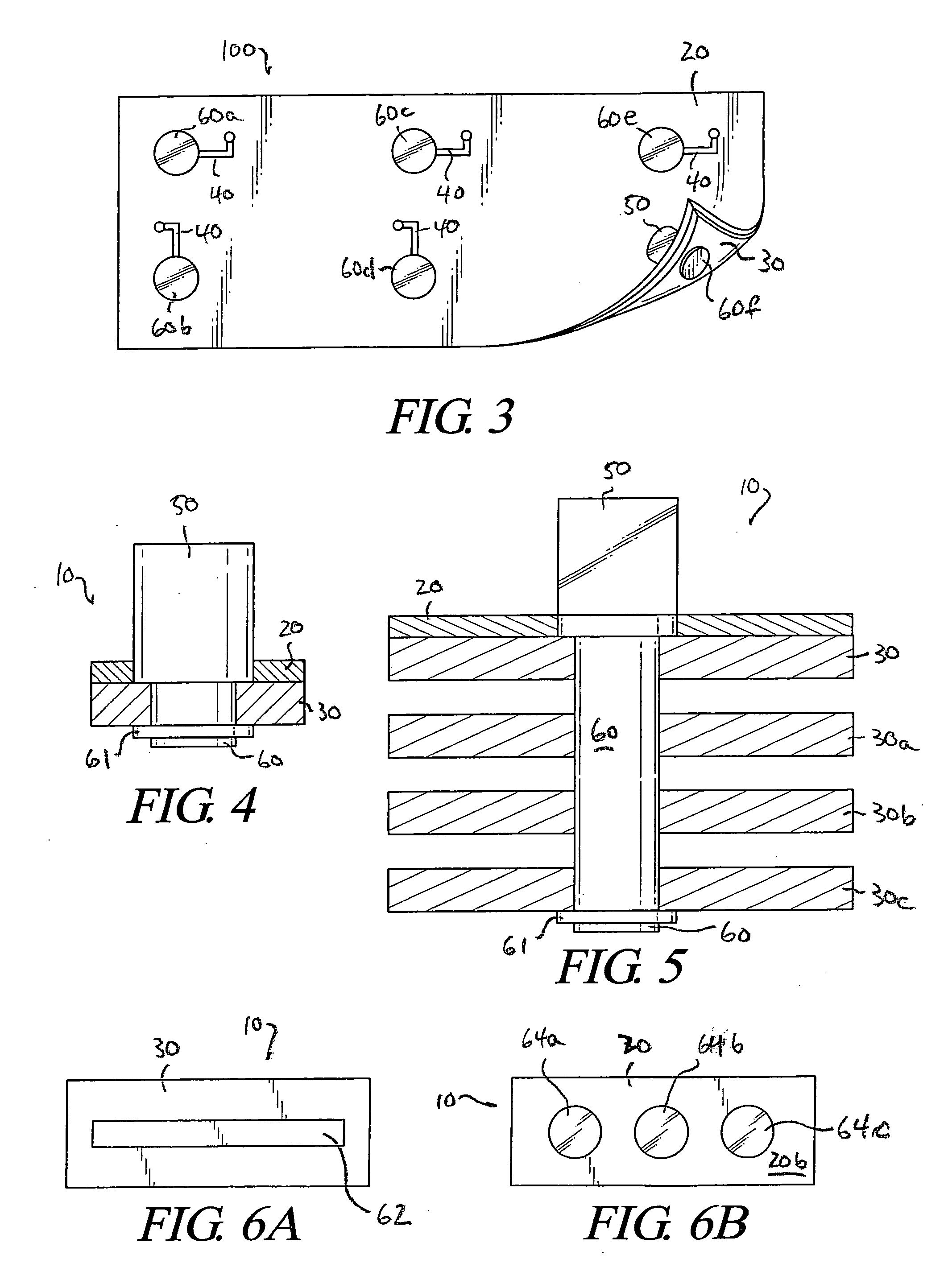
[0077] The present invention provides preferred constructions for and methods of manufacturing graphite heat spreaders having thermal vias. In one embodiment flanged thermal vias are provided having at least one flange which engages with one of the major planar surfaces of the graphite planar element of the graphite heat spreader. Such a flanged via may be attached to the graphite heat spreader either through the use of a push on nut or the use of a second flange which is rigidly connected to the stem of the via. Thus such flanged vias include at least one flange, and either a second flange or a push on nut all of which extend above the surface of the graphite heat spreader element. In another embodiment, flush thermal vias are provided which in the final position are flush with the major planar surfaces of the graphite heat spreader element. Various preferred techniques for manufacturing both embodiments are provided.

[0078] Both embodiments preferably involve the method of manufac...


PUM

PropertyMeasurementUnit
densityaaaaaaaaaa
temperaturesaaaaaaaaaa

Abstract

Constructions for and methods of manufacturing graphite heat spreaders having thermal vias placed therethrough are provided. Thermal vias having one or two flanges are disclosed, as are flush thermal vias. Graphite heat spreaders having surface layers covering the graphite material are provided. Graphite heat spreaders having a layer of cladding for increased structural integrity are provided. Also disclosed are methods of co-forging a graphite heat spreader element with a metal thermal via in place therein.

Description

[0001] This invention is a continuation-in-part of co-pending U.S. patent application Ser. No. 11 / 267,933 filed Nov. 4, 2005, entitled “Heat Spreading Circuit Assembly”, by Reis et al., the details of which are incorporated herein by reference.TECHNICAL FIELD [0002] The present invention relates generally to heat spreaders made from anisotropic graphite planar materials, and particularly to such heat spreaders including thermal vias to aid in transmitting heat through the thickness of the heat spreaders. BACKGROUND OF THE INVENTION [0003] Graphite heat spreaders have previously been proposed to move heat from discrete heat sources. One surface of the spreader is placed against the discrete source and the heat moves from it into the spreader. Heat is then conducted through the spreader and dissipated, from both surfaces of the spreader, to cooler adjacent surfaces by conduction or radiation, or to air by convection. Thick graphite spreaders, with high in-plane thermal conductivity, h...

Claims


Application Information

Patent Timeline
Patent Type & Authority Applications(United States)
IPC IPC(8): H05K7/20
CPCH01L23/3677H01L23/373H05K1/0203H05K1/0204H05K1/182H05K2201/0323H05K2201/10106H05K2201/10416H01L2924/0002F28F13/00F28F21/02H01L2924/00F28F7/00H05K7/20
Inventor REIS, BRADLEYSMALC, MARTINLASER, BRIANKOSTYAK, GARYSKANDAKUMARAN, PRATHIBGETZ, MATTHEWFRASTACI, MICHAEL
Owner NEOGRAF SOLUTIONS LLC
Why Eureka
Try Eureka