

Blood glucose measurement device and metabolic rate measurement device
a measurement device and metabolic rate technology, applied in the field of blood glucose measurement devices and metabolic rate measurement devices, can solve the problems of large device size and high operational cost, and achieve the effect of simple signal processing technique and simple device constitution
- Summary
- Abstract
- Description
- Claims
- Application Information
AI Technical Summary
Benefits of technology
Problems solved by technology
Method used
Image

Examples
example 1
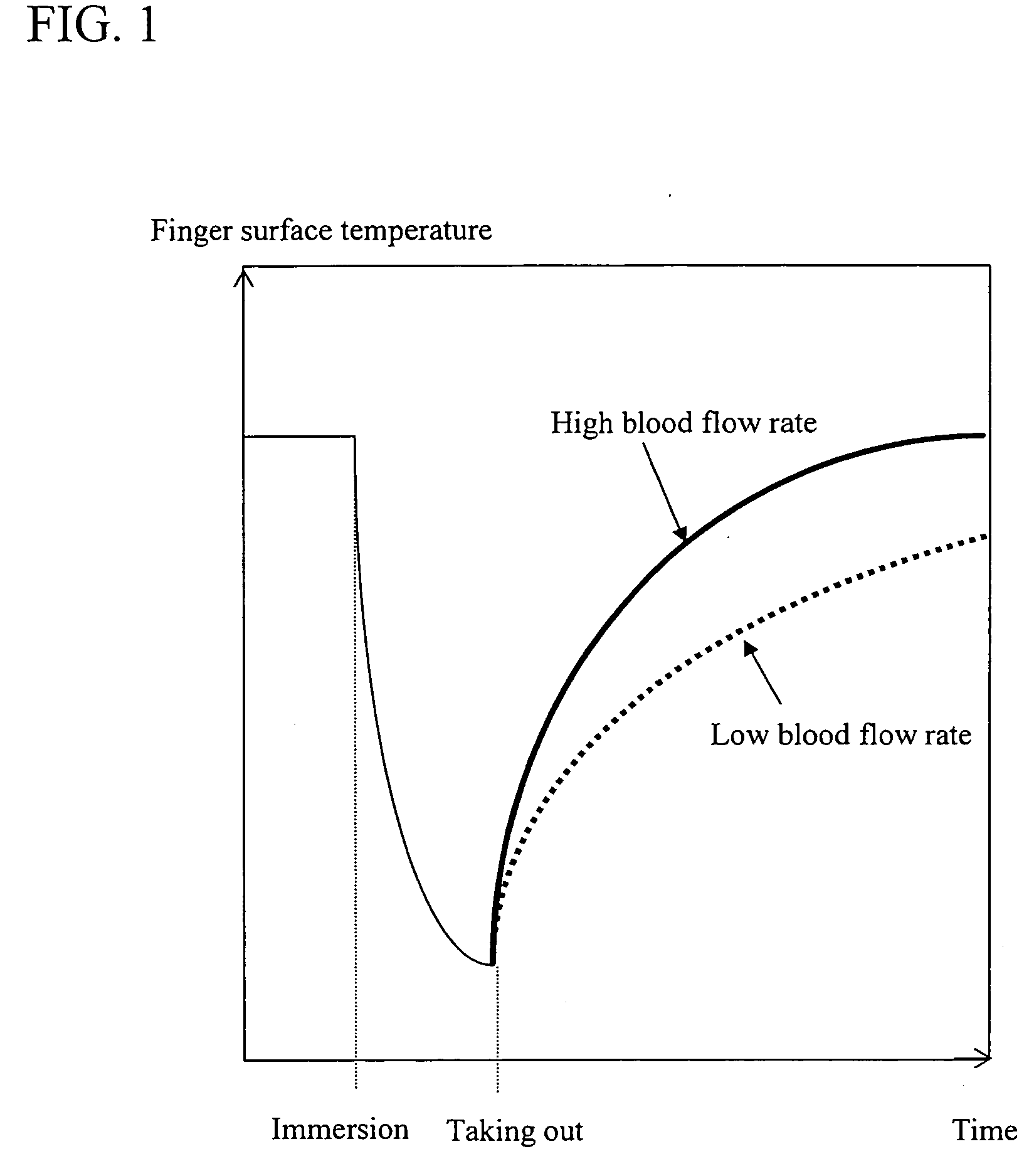
[0044] As described above, a value which is proportional to blood flow rate can be measured when initial temperature of a part such as a fingertip of the human at rest and in thermal equilibrium and the room temperature are first measured and recovery of the skin surface temperature is measured after applying a thermal load to such site. In other words, the minimum data that should be collected are the initial finger temperature, the room temperature, and the change of skin surface temperature. An embodiment of the blood flow measurement system of the present invention based on such principle is shown in FIG. 5. FIG. 5A is a top view of the device, and FIG. 5B is a cross-sectional view taken along lines AB. In this Example, a sensor 501 comprises a contact temperature sensor 511 aligned with a non-contact temperature sensor 512. The contact temperature sensor 511 is the site where the recovery stage is measured, and also, the site by which the thermal load is applied. The non-contac...
example 2
[0060] An example of applying the measurement system of the present invention to the measurement of blood glucose level is described. Japanese Patent Laid-Open No. 2004-329542 discloses that blood glucose level (Glu) can be estimated from a polynomial expression (2) containing n parameters including the parameter representing the blood flow rate.
Glu=f(x1, x2, x3, x4, . . . , xn) (2)
[0061]FIG. 13 is a view showing the details when the unit for measuring blood flow rate shown in FIG. 5 of the present invention is applied to the non-invasive blood glucose measurement device disclosed in Japanese Patent Application Laid-Open No. 2004-329542, supra. FIG. 13A is a top view, FIG. 13B is a cross-sectional view taken along line X-X, and FIG. 13C is a cross-sectional view taken along line Y-Y.
[0062] The temperature measurement unit of a non-invasive blood glucose measurement device described in this Example is the unit measuring the blood flow rate as described above, and the structure an...
example 3
[0095] This Example illustrates an embodiment in which the measurement device of the present invention is used in estimating metabolic rate.
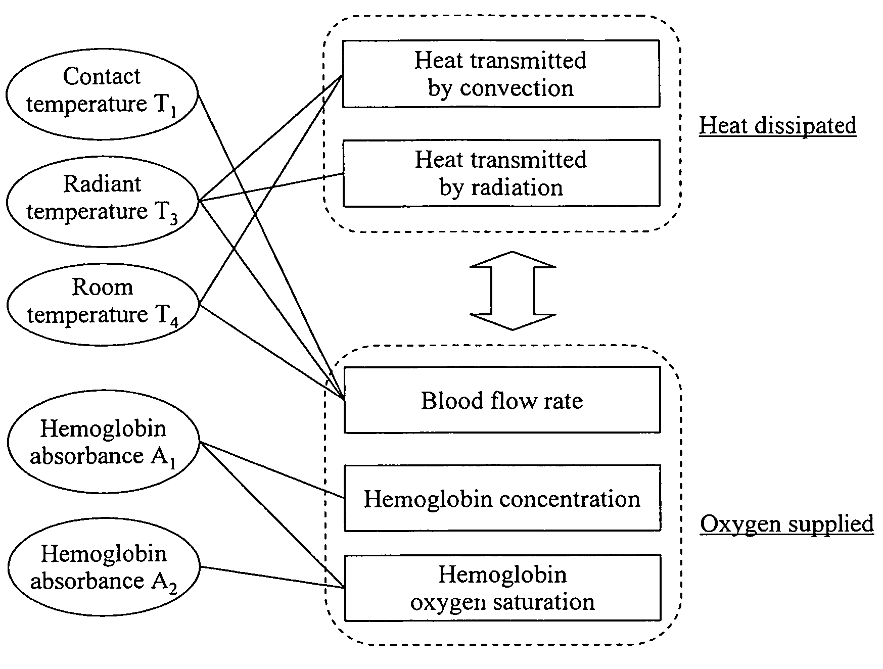
[0096] Based on the thermal control mechanism of human body, the heat produced by metabolism (metabolic heat production) is equal to the sum of the heat accumulated in the body (accumulated heat) and the heat dissipated from the body (dissipated heat). This gives the following equation.
(Metabolic rate of the entire body [metabolic heat production])=(heat accumulated in the entire body)+(heat dissipated from the entire body) (5)
[0097] When body at site ri has an internal temperature T, the site ri has a tissue temperature TT, and the site ri has a heat capacity αi, the heat accumulated in the entire body will be the total of the heat accumulated in each parts, and such heat accumulated in the entire body can be represented by the following equation.
Accumulated heat of the entire body=Σiαi{T(ri)−TT(ri)}
[0098] While the equation as described a...
PUM
| Property | Measurement | Unit |
|---|---|---|
| thermal conductivity | aaaaa | aaaaa |
| heat capacity | aaaaa | aaaaa |
| temperature | aaaaa | aaaaa |
Abstract
Description
Claims
Application Information