Deployment system for an intraluminal medical device

a deployment system and medical device technology, applied in the field of deployment systems for intraluminal medical devices, can solve the problems of insufficient radial strength, risk of unraveling of some of the fibers comprising the braided stent, and the impracticality of using balloon expandable stents in some vessels, so as to prolong the shelf life of the intraluminal medical device, enhance the visualization of the stent, and minimize undesirable or premature delamination

Inactive Publication Date: 2007-05-10
CORDIS CORP
View PDF8 Cites 26 Cited by
  • Summary
  • Abstract
  • Description
  • Claims
  • Application Information

AI Technical Summary

Benefits of technology

[0015] Generally, the stent, stent graft, or segments thereof, is crimped onto the support member in order to aid stability of the stent, stent graft, or segments thereof, during loading and delivery. In some embodiments, however, portions of the support member protrude through open or accessible areas of the stent or stent graft, or segments thereof, so as to releasably grip the stent or stent graft, or segments thereof. Such gripping by protruding portions of the support member secures the stent, stent graft, or segments thereof, to the inner member of the delivery system even more than otherwise occurs by only crimping until delivery is effected, although crimping alone provides sufficient longitudinal stability to the stent, stent graft or segments thereof, to distribute forces effectively throughout the intraluminal medical device during loading and delivery thereof. Where a stent, stent graft or segments thereof is provided with a coating, the portions of the support structure that protrude through the open or accessible areas of the stent, stent graft, or segments thereof, also provide a barrier to the coating. Such barriers can extend the shelf life of the intraluminal medical device, and helps minimize undesirable or premature delamination of a coating from the device, in addition to the gripping function described above.
[0016] In some embodiments, the support member is attached to the inner member of the delivery system using adhesives. In other embodiments, the support member is attached to the inner member by marker bands crimped or swaged over the support member, thereby securing the support member to the inner member. Preferably, one marker band is located at a distal end of the support member, and another marker band is located at a proximal end of the support member. Radiopaque materials may comprise some or all of the marker bands to enhance visualization of the stent, stent graft or segments thereof, and the catheter during delivery and deployment of the intraluminal medical device.

Problems solved by technology

Balloon expandable stents can be impractical for use in some vessels, such as the carotid artery, due to their proximity to the surface of a patient's skin when deployed.
Braided stents, on the other hand, pose other disadvantages, such as insufficient radial strength and the risk of unraveling of some of the fibers comprising the braided stent.
Even self-expanding stents, however, are susceptible to resistive forces during delivery that may cause the stent to undesirably bend, bunch, buckle or break as the stent is attempted to be pushed to its intended treatment site.
Non-uniform deployment of the stent can occur as a result.
Buckling of the stent can further result in undesirable out-of-plane deflections of struts or segments of the stent, which may be particularly prevalent where a series of stents or stent grafts comprise the device.
Such deflections risk penetration of the struts or segments into portions of the delivery sheath, or possibly the vessel wall, that can hinder deployment of the stent.
Buckling can also lead to undesirable accumulations of reactive forces in portions of the stent that results in non-uniform deployment of the stent as described above.
Of course, where resistive forces are so great that breaking of the stent occurs, the stent is no longer usable for its intended purpose.
Resistive forces can also damage coatings where a coating stent is used, thereby also rendering the stent unusable.
The heat required to produce the attachment projections of the inner member tube or sleeve of the '893 or '295 patents can weaken bridging, or other portions, of a stent that is to be delivered however.
Moreover, the requirement of heat to produce the attachment projections and filling of the open lattice structure of a stent is an additional step that can complicate the delivery of the stent, particularly where insufficient heat is provided rendering the stent susceptible to shifting during delivery as a result of under-developed attachment projections or other open lattice filling functions.
Such heat also risks premature, or other, degradation of stent coatings, where the stent to be delivered is provided with such a polymeric, drug or other bio-active agent coating.
The mechanics of such grippers can complicate the delivery and deployment of a stent, particularly where the mechanics of such grippers fail.

Method used


Image

  • Deployment system for an intraluminal medical device
  • Deployment system for an intraluminal medical device
  • Deployment system for an intraluminal medical device

Examples


Embodiment Construction

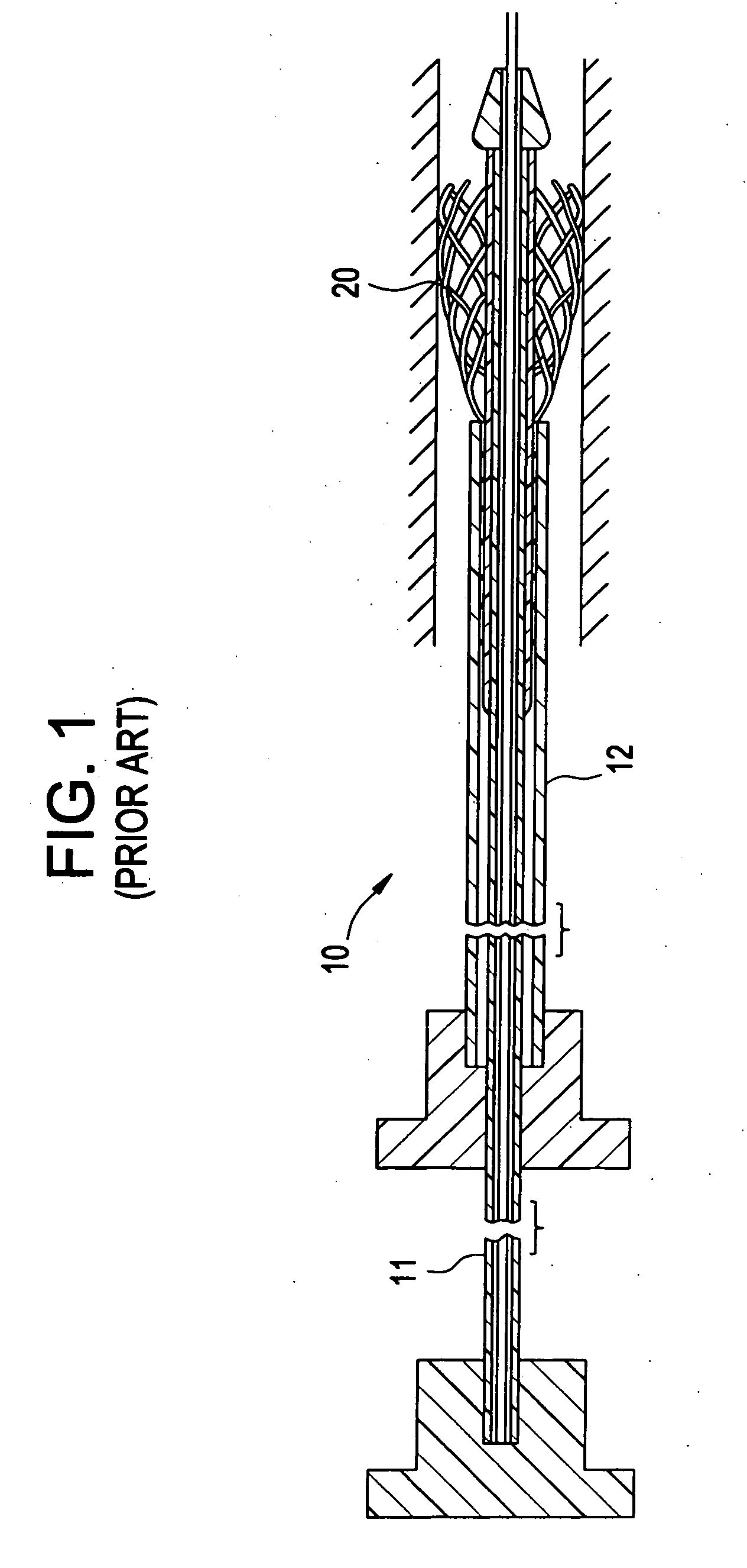
[0028]FIG. 1 illustrates a conventional catheter delivery system 10 for delivering a stent 10 into a patient's vasculature, such as into the coronary artery, the carotid artery, the renal artery, peripheral arteries or veins, and the like. As shown in FIG. 1, a self-expanding stent 20 having an open lattice structure is inserted between an inner member 11 and an outer member 12 at a distal end of the catheter delivery system 10. The stent 20 is self-expandable such that the stent 20 expands as the inner member 11 on which the stent is mounted moves beyond the outer member 12. Because the stent 20 is not secured to the inner member 11 prior to delivery, other than by the overlying outer member 12, expansion of the stent occurs rapidly as the stent 20 emerges from the catheter delivery system 10.

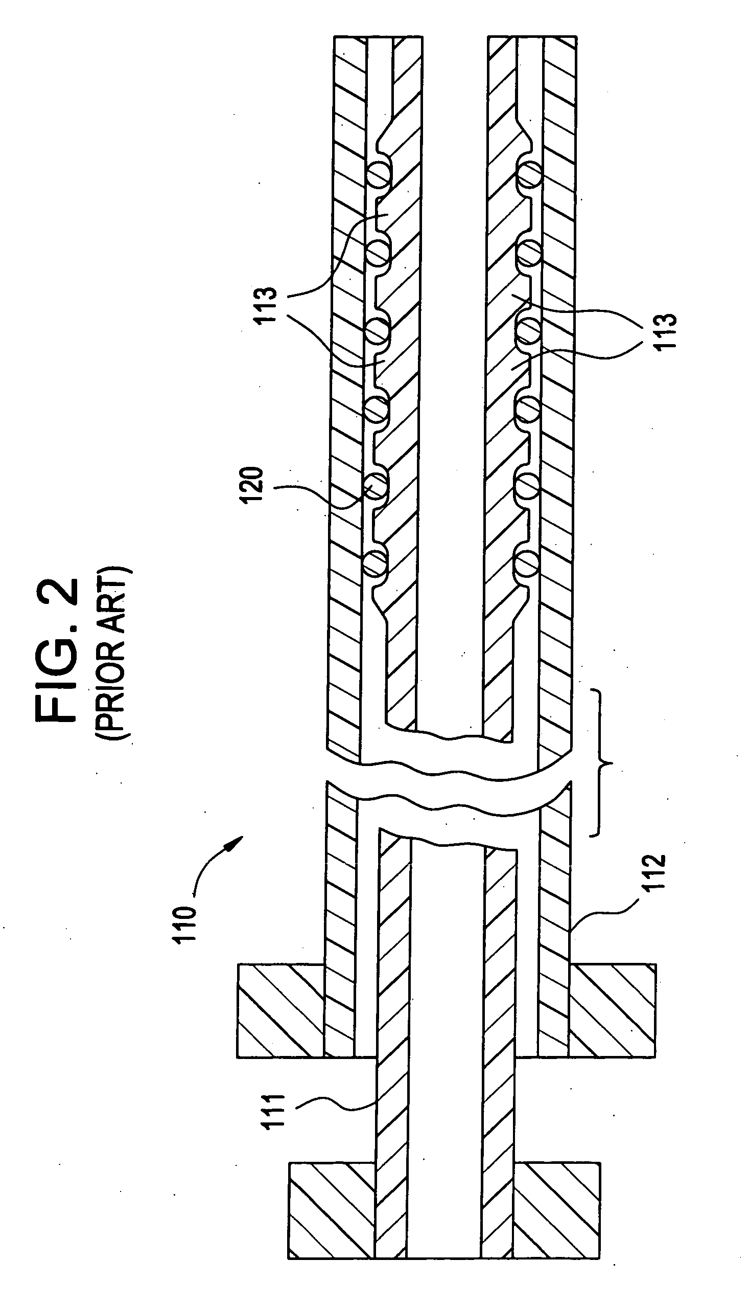
[0029]FIG. 2 illustrates a prior art catheter delivery system 110 that is similar to that described above with respect to FIG. 1, except that a distal end of the inner member 111 is made from...


PUM


Abstract

An intraluminal medical device delivery system that distributes forces more uniformly across an intraluminal medical device during loading and delivery of the device to an intended treatment site. A support member provided on an inner member of a catheter delivery system helps to more uniformly distribute forces across the device by crimping the device over the support member so as to place the support member in a mechanically compressed state during delivery of the device to the intended treatment site. The support member is preferably comprised of a material having a modulus of elasticity that increases when the material is compressed. The mechanical nature of the support member provides increased stability to the device during loading and delivery thereof without providing heat or other preformed or additional mechanical members to the support member. Repositioning of the device is available due to the stability of the device when mounted on the support member. The intraluminal medical device can be a stent, a stent graft, segments thereof, or a series of such stents, stent grafts, or segments thereof.

Description

BACKGROUND OF THE INVENTION [0001] 1. Field of the Invention [0002] The invention relates to a deployment system for an intraluminal medical device. More particularly, the invention relates to a deployment system having a support member on an inner member of a catheter that helps distribute loads more uniformly througout the intraluminal medical device during loading and delivery. [0003] 2. Related Art [0004] Percutaneous transluminal angioplasty (PTA) is a therapeutic medical procedure used to increase blood flow through an artery. In this procedure, an angioplasty balloon is inflated within the stenosed vessel, or body passageway, in order to shear and disrupt the wall components of the vessel to obtain an enlarged lumen. [0005] More recently, transluminal prostheses, such as stents, have been used for implantation in blood vessels, biliary ducts, or other similar organs of a patient in order to open, dilate or maintain the patency thereof. Such stents are often referred to as bal...

Claims


Application Information

Patent Timeline
Patent Type & Authority Applications(United States)
IPC IPC(8): A61F2/06
CPCA61F2/95A61F2250/0018
Inventor BUZZARD, JON D.HOO, BRUCE A.JACKSON, KAREN P.VALDES, FRANCISCOWIDENHOUSE, CHRISTOPHER W.
Owner CORDIS CORP
Why Eureka
Try Eureka