
Fast, low offset ground sensing comparator

a ground sensing comparator and low offset technology, applied in the field of voltage comparators, can solve the problems of high offset, low efficiency, high offset of cross-coupled comparators, etc., and achieve the effects of small power consumption, wide bandwidth, and increased gain and response tim

Active Publication Date: 2007-05-17
VIA TECH INC
View PDF10 Cites 21 Cited by
  • Summary
  • Abstract
  • Description
  • Claims
  • Application Information

AI Technical Summary

Benefits of technology

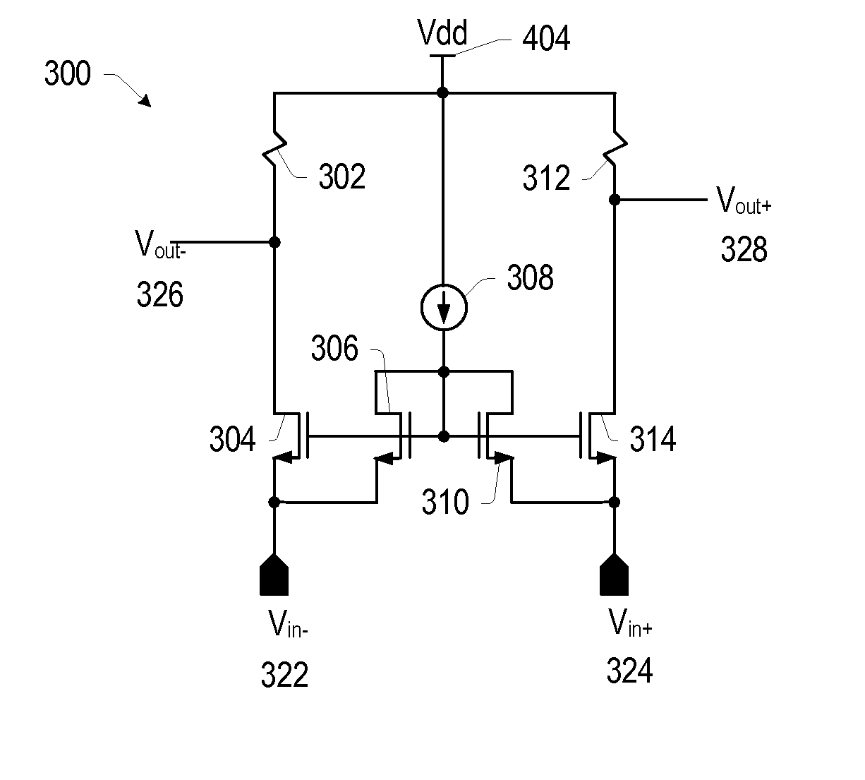
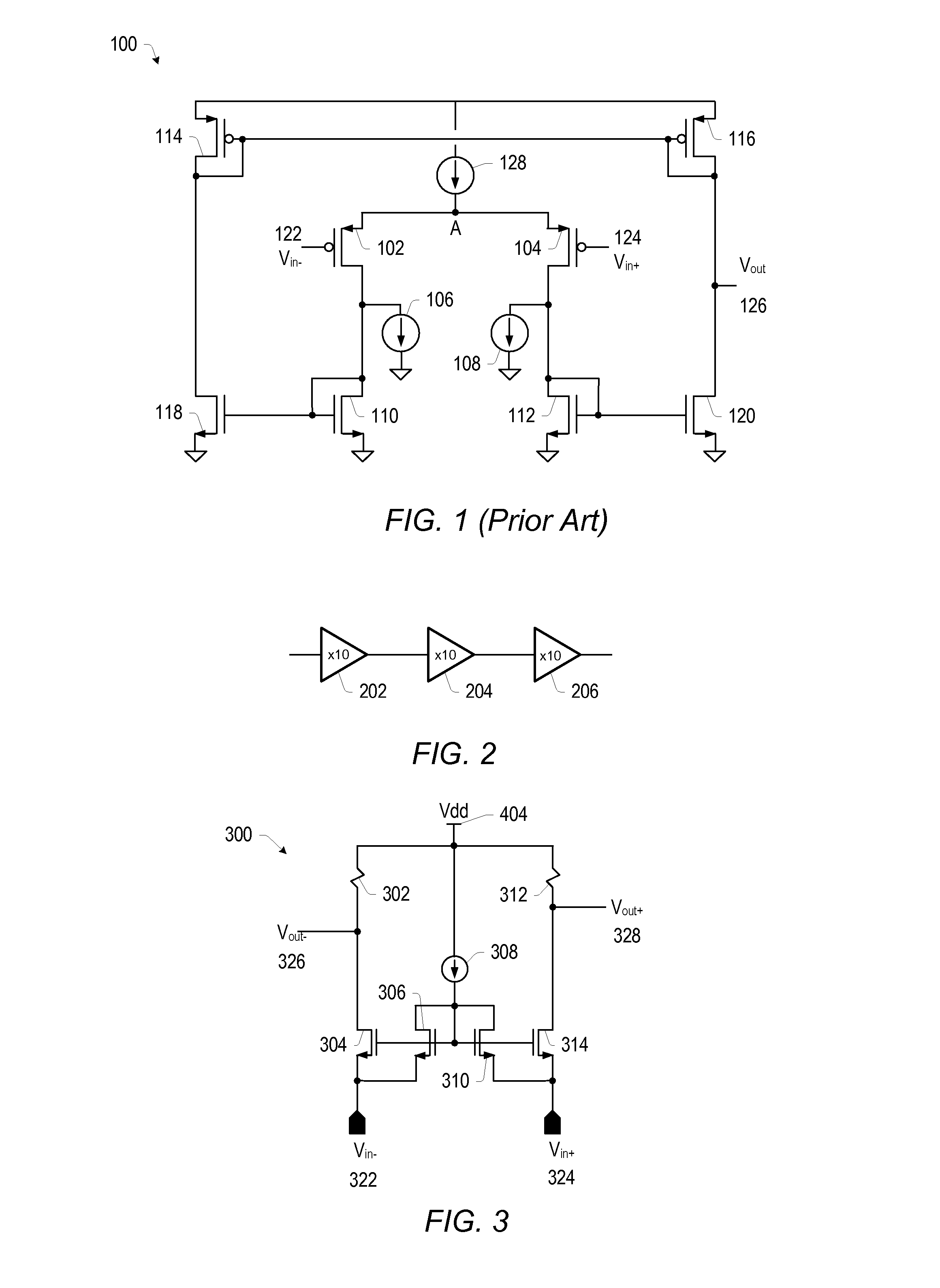
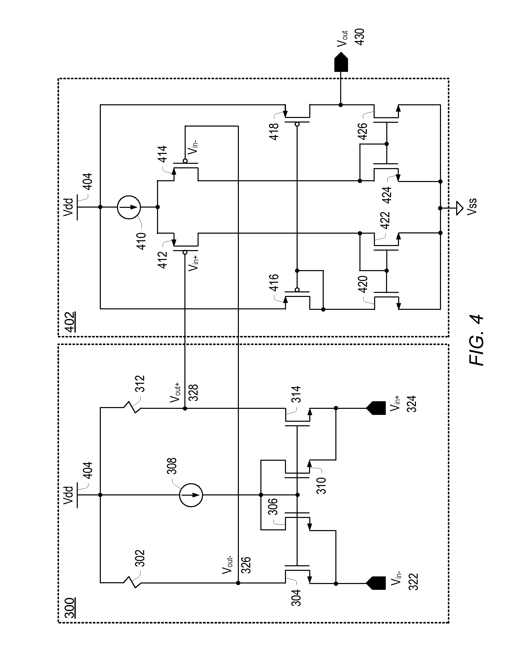
[0008] In one set of embodiments, a fast, accurate, low offset comparator may be configured with multiple stages. A low gain, low input impedance, and fully differential common-gate amplifier may be configured as a first stage in the multi-stage comparator, providing a wide bandwidth for small power consumption. The first stage may be coupled to a second stage comprising a differential input current-mirror amplifier, which may perform differential to single-ended conversion. The single-ended output of the second stage may serve as the input into a latch, which may be a bistable set-reset (SR) latch configured to increase the gain and response time while protecting against multiple switching, with the output of the latch serving as the output of the comparator.
[0009] The multi-stage comparator may achieve a high power-to-speed ratio and low offset by providing a current input into the first stage, in which the respective source terminals of two gate-coupled NMOS devices may be configured as the pair of differential inputs corresponding to the inputs of the comparator. In some embodiments, the power-to-speed ratio may thereby be improved by at least a factor of 5, with no large voltage swings on at least the internal nodes of the first stage. Overall gain of the comparator may be increased by configuring multiple gain stages—e.g. two or more stages—that may comprise a series cascade of low gain stages capable of providing a broader bandwidth than a single stage with an equivalent gain. For example, a three-stage, 10×10×10 gain may facilitate the design of a comparator with a broader bandwidth than one with a single stage gain of 1000. The resulting comparator may be configured in a switching power regulator, where it may be disabled when the opposite switch (PMOS) is enabled. Furthermore, the comparator may operate with fast response times, a small offset, and low quiescent current, with protection against multiple switching.

Problems solved by technology

Open loop, uncompensated two-stage operational amplifier (op-amp) based comparators implemented with PMOS (P-channel Metal Oxide Semiconductor) input devices are capable of sensing ground level, typically have a high gain, but may be rather slow when consuming low power.[1]Generally, PMOS input, cross-coupled comparators have a high offset and feature a low gain, but are not suitable for sensing near zero-level (ground) voltages.
A low DC gain would in turn lead to comparator 100 having a high offset and operating with low efficiency.

Method used


Image

  • Fast, low offset ground sensing comparator
  • Fast, low offset ground sensing comparator
  • Fast, low offset ground sensing comparator

Examples


Embodiment Construction

[0019] As used herein, a “pair of differential inputs” refers to a pair of inputs configured as a differential input pair, and a “pair of differential outputs” refers to a pair of outputs configured as a differential output pair. For example, a differential amplifier may have a pair of differential inputs and a pair of differential outputs, with the pair of differential inputs comprising a Vin+ and a Vin− input, and similarly, a pair of differential outputs comprising a Vout+ and a Vout− output. A “single-ended output” refers to a single output as opposed to a pair of differential outputs. A “diode-connected transistor” refers to a transistor having its control terminal (e.g. a gate terminal for MOS devices) coupled to its input terminal (e.g. a drain terminal for MOS devices).

[0020] A fast, accurate and low offset comparator capable of sensing ground level may be configured with multiple gain stages. In one set of embodiments, the first gain stage may be a low gain, low input-impe...


PUM


Abstract

A fast, accurate, low offset comparator may be configured with multiple gain stages. A low gain, low input impedance, and fully differential common-gate amplifier may be configured as a first stage in the multi-stage comparator, providing a wide bandwidth for small power consumption. The inputs of the comparator may comprise a pair of differential inputs at respective source terminals of gate-coupled metal oxide semiconductor (MOS) devices configured in the input stage of the common-gate amplifier. A pair of differential outputs of the first stage may be coupled to a pair of differential inputs of a second stage, which may be a differential input current-mirror amplifier that may perform differential to single-ended conversion. The single-ended output of the second stage may serve as the input into a latch, which may be a bistable set-reset (SR) latch configured to increase the gain and response time while protecting against multiple switching, with the single-ended output of the latch configured as the output of the comparator.

Description

[0001] This application claims benefit of priority of U.S. provisional application Ser. No. 60 / 595,056 titled “Fast, Low-Offset Ground Sense Comparator”, filed Jun. 2, 2005.BACKGROUND OF THE INVENTION [0002] 1. Field of the Invention [0003] This invention relates to voltage comparators, and more particularly to designing fast comparators that can accurately compare signals to ground level. [0004] 2. Description of the Related Art [0005] Comparators are devices that typically compare two voltages or two currents, switching their respective outputs to indicate which of the two input signals is larger. Oftentimes comparators are analog circuits used in a variety of applications. One implementation of comparators may be directed towards detecting the level of an input signal relative to a zero-level voltage, or ground, in switching power regulators operating in a PFM (pulse-frequency-modulation) mode. Many different types of comparators exist, each with different advantages and disadvan...

Claims


Application Information

Patent Timeline
Patent Type & Authority Applications(United States)
IPC IPC(8): H03K5/22
CPCH03K5/2481
Inventor HO, DANIEL
Owner VIA TECH INC
Learn More