Surface Plasmon Resonance Sensing System

Inactive Publication Date: 2007-05-17
NATIONAL CHUNG CHENG UNIV
View PDF2 Cites 22 Cited by
  • Summary
  • Abstract
  • Description
  • Claims
  • Application Information

AI Technical Summary

Benefits of technology

[0010] Whereas the present invention is adapted with the optical fiber with noble metal nano-particles instead of the conventional prism, the size of the SPR sensing syst

Problems solved by technology

Furthermore, LSPR sensors can be constructed by simple and low-cost optica

Method used


Image

  • Surface Plasmon Resonance Sensing System
  • Surface Plasmon Resonance Sensing System
  • Surface Plasmon Resonance Sensing System

Examples


Embodiment Construction

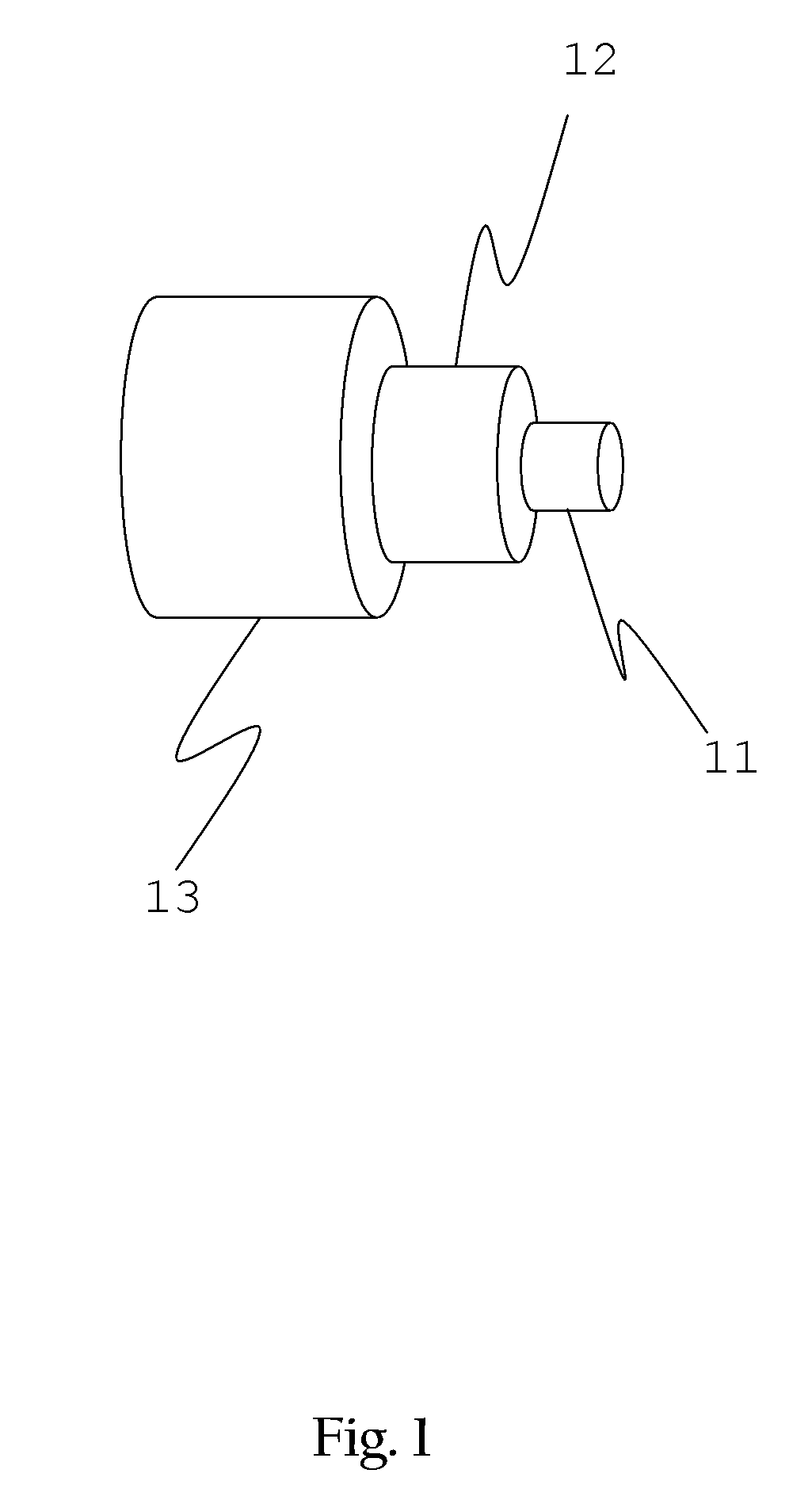
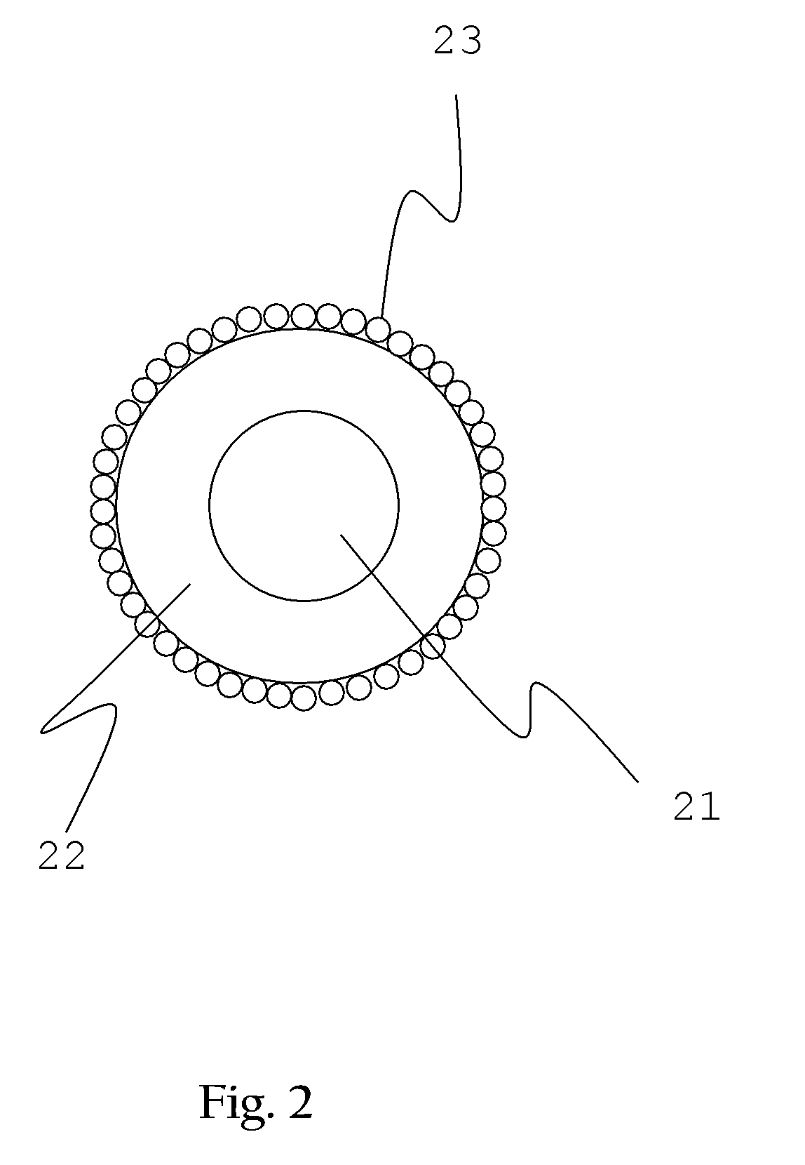
[0017] Referring to FIG. 1 for a schematic view showing construction of an optical fiber, the optical fiber is essentially comprised of three layers, respectively the innermost a core 11, a cladding 12 in the middle, an outermost protection 13 with materials and functions different from one another. As illustrated in FIG. 2 for a schematic view showing the optical fiber device covered with noble metal nano-particles, the optical fiber device is an optical fiber wherein a portion of a protection layer and a cladding layer are stripped off and preserved only a core layer 21 and, if exist, a residual cladding layer 22, and then a noble metal nano-particle layer 23 is covered up the surface of the optical fiber device. It should be noted that the cladding layer 22 could be totally stripped off to directly cover up the noble metal nano-particle layer.

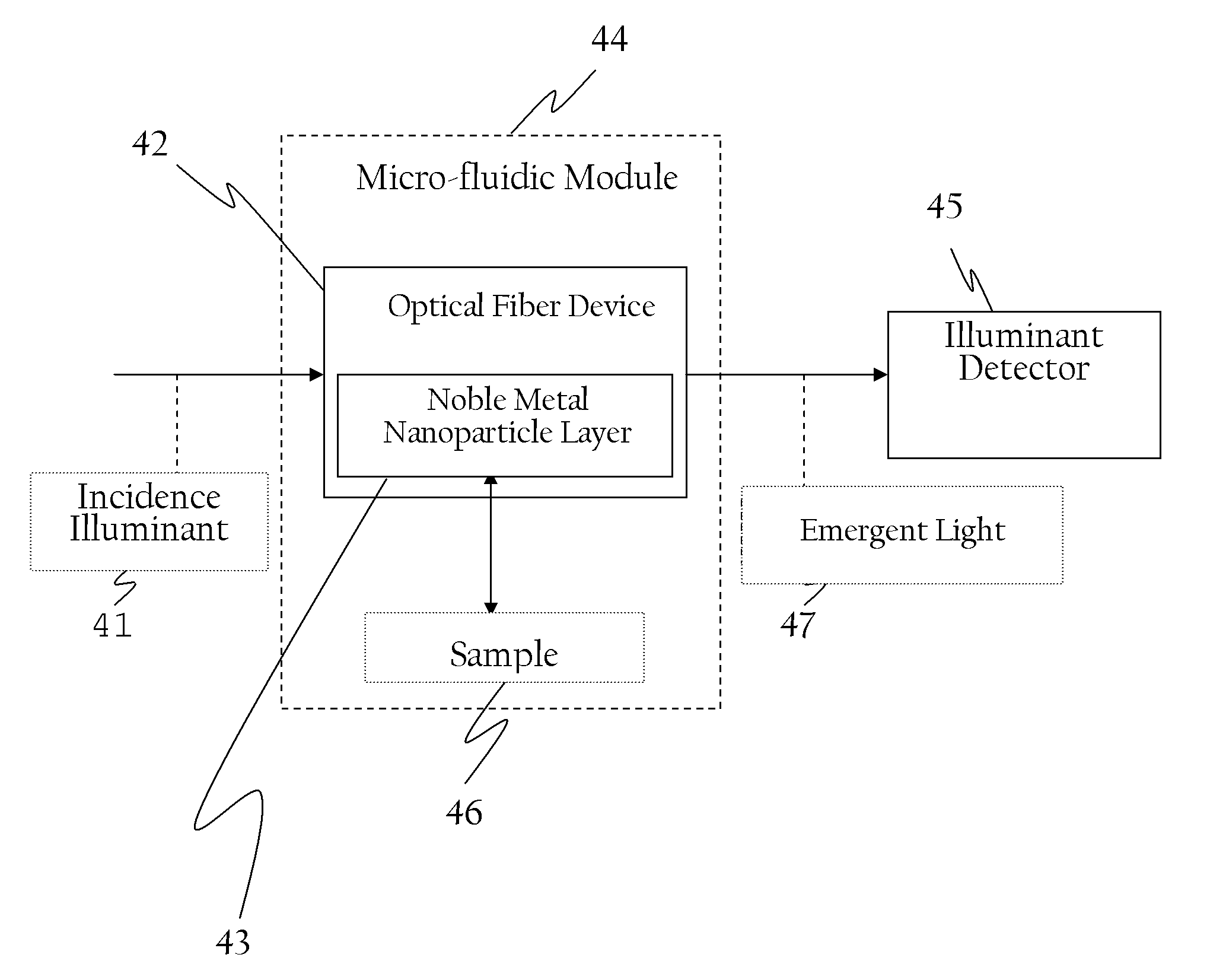
[0018] The present invention is related to a sensing system integrated with a micro-fluidic chip and the optical fiber clad by noble metal...


PUM


Abstract

A surface plasmon resonance sensing system comprised of an incidence illuminant, a modified optical fiber, a layer of gold nanoparticles, a micro-fluidic module, and an illuminant detector; the modified optical fiber related to an optical fiber stripped off a portion of its protection layer and a cladding layer; the layer of noble metal nanoparticles covering over the modified optical fiber; the micro-fluidic module related to a micro-fluidic chip for containing the modified optical fiber and a sample; and the illuminant detector operating to detect the light emitted from the modified optical fiber.

Description

BACKGROUND OF THE INVENTION [0001] (a) Field of the Invention [0002] The present invention is related to a surface plasmon resonance (SPR) sensing system, and more particularly to an SPR sensing system, apparatus, and method excited by noble metal nanoparticles. [0003] (b) Description of the Prior Art [0004] Surface plasmon resonance phenomenon is that when a light source illuminates a metal surface at a fixed incident angle, the reflection intensity detected by a light detector would be near zero, which means the reflectivity of the metal film is near zero. The light which is not reflected will propagate along interface direction at a certain velocity to resonantly excite the surface plasmon of the metal. The method of measuring the reflected light is known as Attenuated Total Reflection (ATR). [0005] A surface plasmon resonance sensing system uses a sensing system made by surface plasmon resonance phenomenon. Because the surface plasmon resonance sensor has high sensitivity, is la...

Claims


Application Information

Patent Timeline
IPC IPC(8): G01N21/55
CPCB01L3/5027G01N21/554G01N21/7703G01N2021/258
Inventor CHAU, LAI-KWANHSIEH, WEN-HSINHSU, WEI-TINGCHEN, PO-LIANG
Owner NATIONAL CHUNG CHENG UNIV
Why Eureka
Try Eureka