That is, storage tank owners are willing to invest huge sums of money in both the maintenance and inspection of such tanks.
As one could imagine, there are a wide range of problems associated with maintaining storage tank integrity, particularly with
above ground storage tanks.
Given the enormous dimensions of
above ground tanks, the corrosive products contained within the tanks, the incredible
mass of the stored product, and the
extreme weather conditions the tanks are subjected to; it is plain to see that above ground storage tank leaks are an all-to-common problem.
Given the limited number of systems capable of meeting the EPA's
underground storage tank leak
detection threshold and the added difficulties associated with above ground tanks, the difficulty in protecting against and detecting leaks is easily seen.
However, the recognized difficulty in preventing storage tank leaks does not mitigate the duties or liabilities imposed on responsible parties.
Tremendous environmental and economic consequences and the
threat of litigation and
clean up costs associated with storage tank leaks force responsible parties to invest large sums of money in the maintenance and inspection of the tanks.
Tank inspections are costly with respect to the amount of money spent, the danger presented to the inspectors and the environment, and production
downtime.
In fact, these inspections often remove a tank from service for more than one month.
The
threat of liability also forces responsible parties to spend money unnecessarily for the maintenance of these tanks.
Currently, responsible parties are, in some countries, being incarcerated as a direct result of storage tanks leaks.
These leaks have contaminated surrounding ground water, some of which serves as drinking water for local residents.
Each day the shuttered facilities remain inoperative adds to an already tremendous amount of money lost.
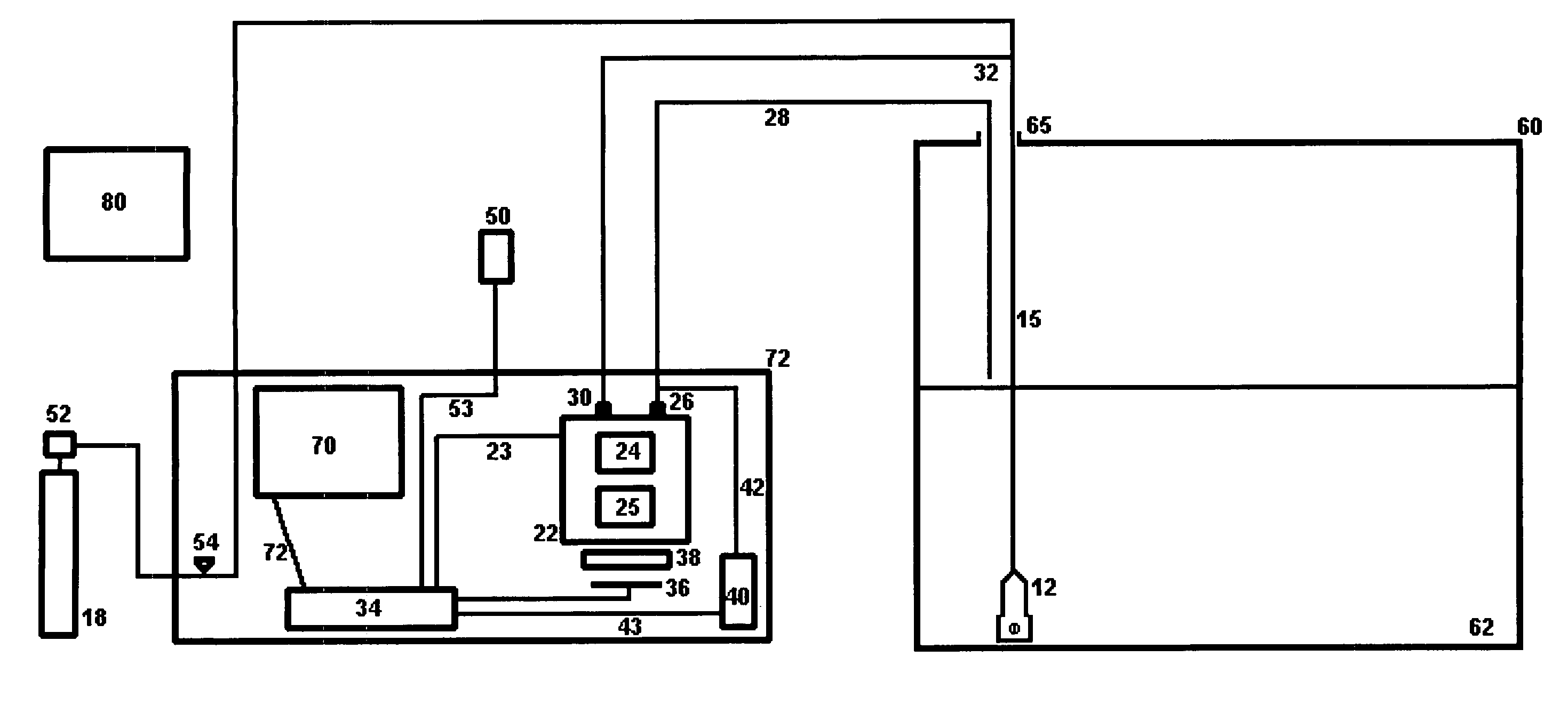
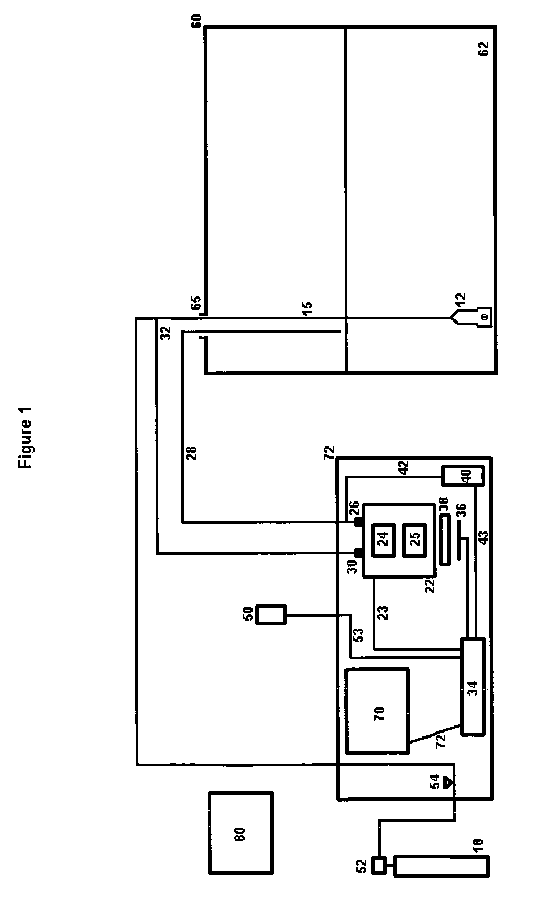
Presently available leak detection systems lack detection thresholds low enough to detect leaks down to permissible upper leakage limits for above ground storage tanks.
Storage tank leak detection systems are known in the art; however, these products are fraught with problems.
Further, some detection devices can only be used when the storage tank is empty, and no known system or method ensures a comprehensive inspection of the tank.
The most common form of such a system is “vacuum box testing;” however, this system is intended only for weld joints and is not usually applied to the entire tank bottom.
Magnetic flux floor scanning is also used, but is not effective at examining the area of the floor surface close to the surface walls or where there are physical obstructions.
Gas detection is also used, but the types of materials stored in the tank can obstruct this method.
However, even large volume changes produce only small level changes, as the cross-sectional area of the liquid surface in these tanks is very large.
This, combined with differential expansion and temperature change of the stored liquid and its vapor, make this type of detection system inconsistent and very nearly worthless.
Present
mass measurement leak detection systems in the art are limited by tank shell variations resulting from temperature effects on tank shell plating.

