Radiation detection circuit and apparatus for radiographic examination

Inactive Publication Date: 2007-05-24
SUMITOMO HEAVY IND LTD
View PDF8 Cites 24 Cited by
  • Summary
  • Abstract
  • Description
  • Claims
  • Application Information

AI Technical Summary

Benefits of technology

[0013] Embodiments of the present invention provide a radiation detection circuit having a simple circuit configuration and an appar

Problems solved by technology

However, since the delay circuit 101 of the detection circuit 100 shown in FIG. 1 is normally formed by connecting many operational amplifiers, the configuration of the detection circuit 100 is complicated.
However, adjusting the delay time requires changing the number of operational amplifiers and the de

Method used


Image

  • Radiation detection circuit and apparatus for radiographic examination
  • Radiation detection circuit and apparatus for radiographic examination
  • Radiation detection circuit and apparatus for radiographic examination

Examples


first embodiment

1. First Embodiment

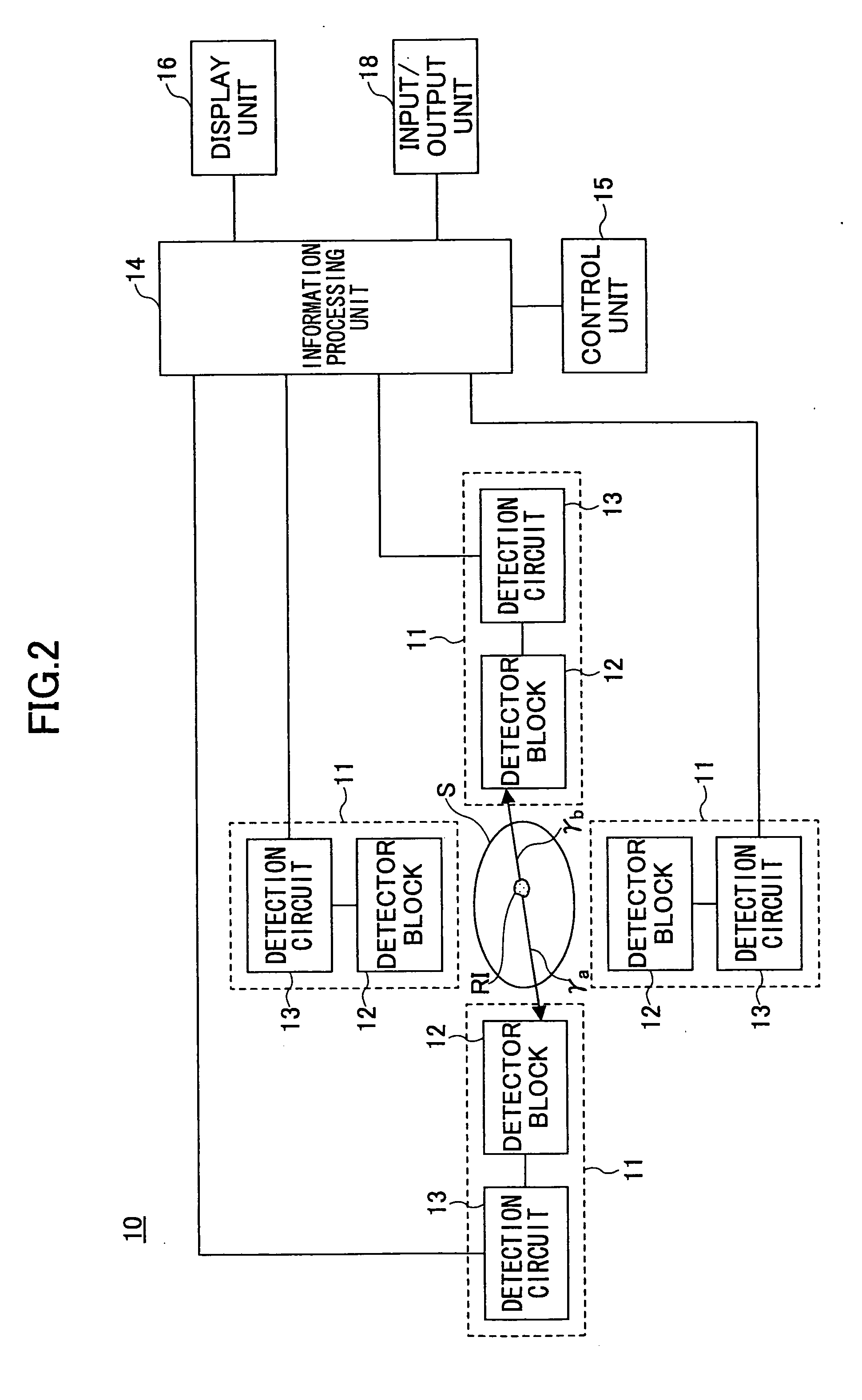
[0032]FIG. 2 is a block diagram illustrating an exemplary configuration of a PET apparatus according to a first embodiment of the present invention. As shown in FIG. 2, a PET apparatus 10 is configured so as to surround an object S and includes detection units 11 for detecting gamma rays each of which detection units 11 includes a detector block 12 and detection circuit 13; an information processing unit 14 for processing detection data and reconstructing image data showing detected positions of positron nuclides in the object S; a display unit 16 for displaying the image data; a control unit 15 for controlling the movement of the object S and the detection units 11; and an input / output unit 18 including a terminal for sending instructions to the information processing unit 14 and the control unit 15 and a printer for outputting image data.

[0033] Prior to examination, a diagnostic agent labeled by a positron nuclide RI is introduced into the object S. The detecti...

second embodiment

2. Second Embodiment

[0080] A PET apparatus according to a second embodiment of the present invention is described below. A PET apparatus according to the second embodiment of the present invention has a configuration similar to that of a PET apparatus according to the first embodiment except the configuration of the detection circuit.

[0081] The detector blocks and detectors of a PET apparatus according to the second embodiment have configurations similar to those of the detector blocks and detectors of a PET apparatus according to the first embodiment. Therefore, descriptions of parts having similar configurations are omitted.

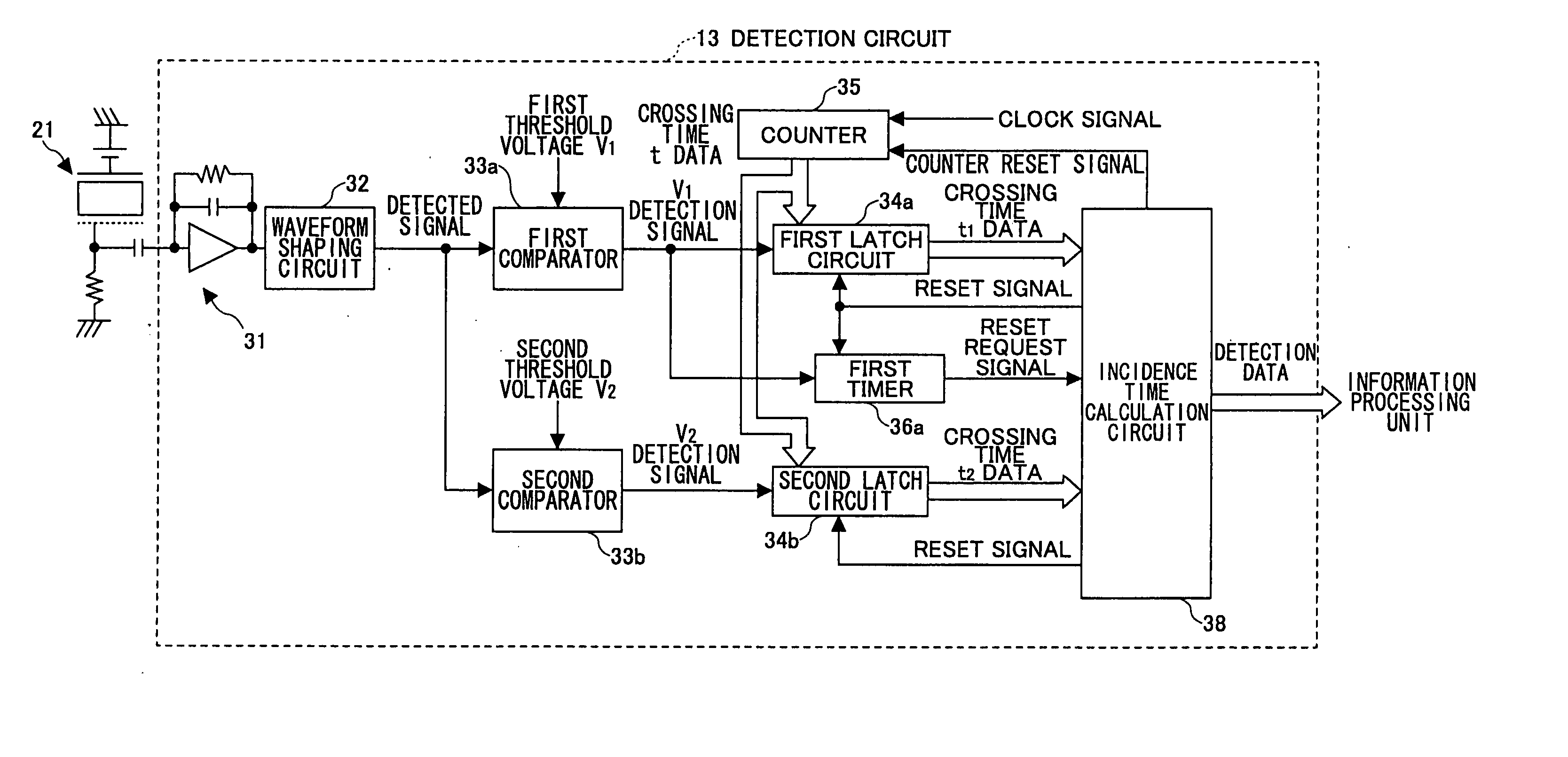
[0082]FIG. 8 is a block diagram illustrating an exemplary detection circuit of a PET apparatus according to the second embodiment of the present invention. In FIG. 8, the same reference numbers are used for parts corresponding to those shown in FIG. 5, and descriptions of those parts are omitted.

[0083] As shown in FIG. 8, the detection circuit 40 includes a ...

third embodiment

3. Third Embodiment

[0098] A third embodiment of the present invention is described below. In the third embodiment, some changes are made to the detection circuit 40 according to the second embodiment.

[0099]FIG. 11 is a block diagram illustrating an exemplary detection circuit of a PET apparatus according to a third embodiment of the present invention. In FIG. 11, the same reference numbers are used for parts corresponding to those shown in FIG. 8.

[0100] An exemplary detection circuit of a PET apparatus shown in FIG. 11 is formed on three substrates 41, 42, 43. On the substrate 41, a crystalline application specific integrated circuit (ASIC) is formed. On the substrate 42, a preamplifier circuit 31, a waveform shaping circuit 32, a first comparator 33a, a second comparator 33b, a third comparator 33c, and an encoder 44 are formed. On the substrate 43, a first latch circuit 34a, a second latch circuit 34b, a counter 35, a first timer 36a, a second timer 36b, a decoder 45, and an inc...


PUM


Abstract

An apparatus for radiographic examination includes a detection unit including a detector configured to detect a gamma ray emitted from a radioactive isotope in an object and to output a detected signal, a first measurement unit configured to determine a first crossing time at which a pulse height of the detected signal becomes substantially equal to a first threshold value, a second measurement unit configured to determine a second crossing time at which the pulse height of the detected signal becomes substantially equal to a second threshold value, and an incidence time calculation unit configured to calculate a starting time of the detected signal based on the first crossing time and the second crossing time and to output detection data; and an information processing unit configured to determine distribution of radioactive isotopes in the object based on multiple sets of said detection data.

Description

BACKGROUND OF THE INVENTION [0001] 1. Field of the Invention [0002] The present invention generally relates to a radiation detection circuit and an apparatus for radiographic examination, and more particularly relates to a radiation detection circuit and an apparatus for radiographic examination that detect two gamma rays emitted from a radioactive isotope in the object at the same time. [0003] 2. Description of the Related Art [0004] Positron emission tomography apparatuses are being used to obtain detailed information on the object. Before a diagnosis using a PET apparatus, diagnostic agents labeled by positron nuclides are introduced into the object by injection or inhalation. The diagnostic agents introduced into the object accumulate in a body part having a function corresponding to the diagnostic agents. For example, diagnostic agents made of saccharide accumulate preferentially in a part of the object where metabolism is high, for example, cancer cells. The positron nuclide o...

Claims


Application Information

Patent Timeline
IPC IPC(8): G01T1/24
CPCG01T1/249A61B6/037G01T1/247G01T1/2985
Inventor AOKI, KENICHI
Owner SUMITOMO HEAVY IND LTD
Why Eureka
Try Eureka