Power generation methods and systems

a technology of power generation and power supply, applied in the direction of electric generator control, lighting and heating apparatus, machines/engines, etc., can solve the problems of increasing the cost of electricity, the number of people in the world who do not have access to electricity, cooling, or reliable heating at low cost, and the current cost of traditional power generation methods and systems

Inactive Publication Date: 2007-05-31
RES SCI
View PDF27 Cites 74 Cited by
  • Summary
  • Abstract
  • Description
  • Claims
  • Application Information

AI Technical Summary

Benefits of technology

[0033]FIG. 2A is a cross-sectional view of a first version heat generator (boiler) for the embodiment of FIG. 1,

Problems solved by technology

Many problems currently exist for traditional power generation methods and systems.
Still, there are more than two billion people in the world who do not have access to electricity, cooling, or dependable heating at low cost.
Therefore, the cost of electricity will keep going up.
Current electric utility companies are limited by production capacity to increase their electricity generation.
To increase generation, these companies must build additional plants which require substantial capital investments, political issues of where to locate the plants, lengthy permit procedures lasting several years, cost overruns, which make the traditional method of building additional plants undesirable.
Using nuclear power, oil burning plants, and coal burning plants, adds further environmental problems for those seeking to build electricity generating power plants.
Thus, building more and more plants is not a practical solution.
Next, the electricity being transmitted loses efficiency while it is being transmitted over transmission lines (i.e. wires, substations, transformers) so that by the time the electricity reaches the end user, an additional 28% (twenty eight percent) energy (efficiency) is lost.
Approximately 70% of the energy (fuel) used in the production of electricity is lost as heat (which is rejected to the environment) because heat energy cannot be efficiently transmitted over long distances.
But there still are transmission losses of some 28% (twenty eight percent) so that by the time electricity reaches the end user only some 22% (twenty two percent) of the actual energy source is converted to electrical power.
However, none of these patents solves all the problems of the wasteful energy conversion methods and systems currently being use

Method used


Image

  • Power generation methods and systems
  • Power generation methods and systems
  • Power generation methods and systems

Examples


embodiment 2000

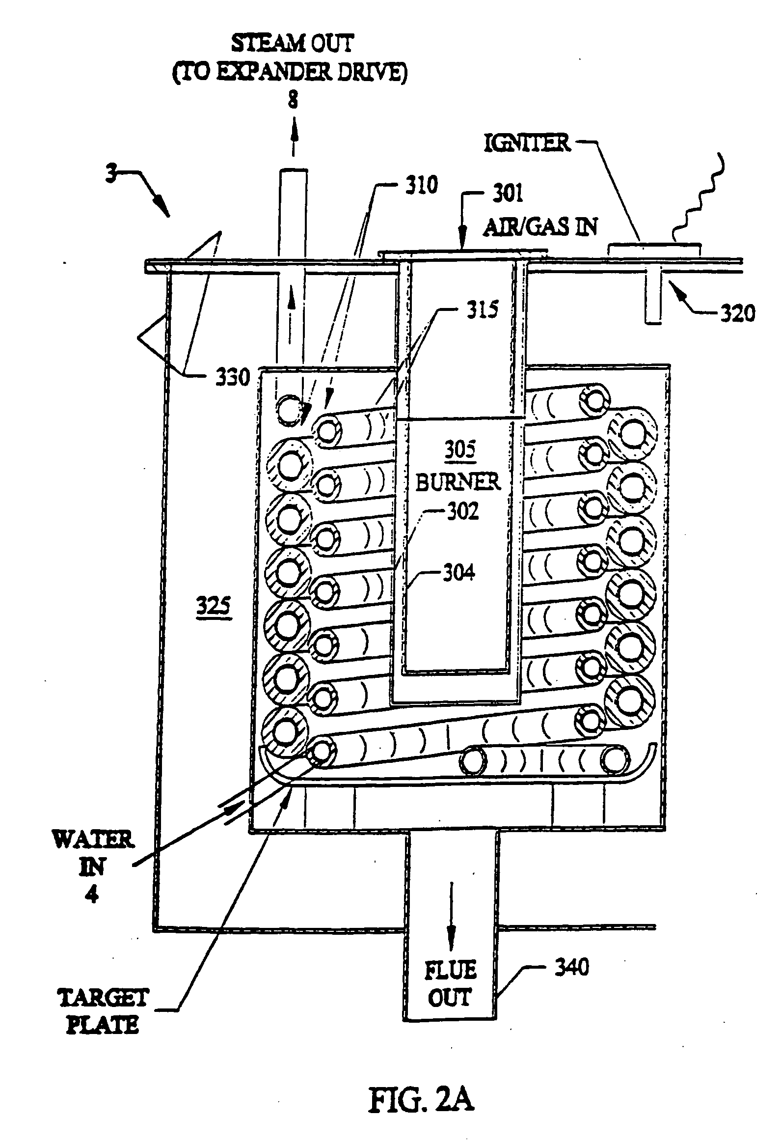
[0104]FIG. 14 shows a third preferred embodiment 2000 for powering a mechanically driven air conditioning compressor 2510 using the novel steam generator 2100, expander drive 2400 and steam condenser 2200 of the invention. The steam generator 2100 referenced above in FIGS. 2A and 2B turns water into steam by burning a renewable or non-renewable fuel source such as natural gas, propane, or hydrogen or any other vaporous or liquid fuel. The hot pressurized steam enters expander 2400 where it is expanded (reduced in pressure and temperature and increased in volume) producing the work used to rotate output driveshaft 2450. The output drive shaft is mechanically connected to a direct drive air conditioning compressor 2510 and used to compress the refrigerant used in the cooling process. The remaining air conditioning system components would be identical to those used in a standard off-the-shelf high efficiency air conditioning unit 2550 (fan, condenser and motor for supplying cooled air)...

embodiment 3000

[0105]FIG. 15 shows a fourth preferred embodiment 3000 for driving an electric generator 3500, or alternator, supplying electricity to any electrically powered device or stand alone end use system using the novel steam generator 3100 (boiler 8FIGS. 2A and 2B), expander drive 3400 and steam condenser 3200 of the invention. The steam generator 3100 referenced above in FIGS. 2A and 2B turns water into steam by burning a renewable or non-renewable fuel source 22 such as natural gas, propane or hydrogen, or any other vaporous or liquid fuel. The hot high pressure steam enters the expander 3400 where it is expanded (reduced in pressure and temperature and increased in volume) producing the work used to rotate output driveshaft 3450. The output driveshaft is mechanically connected to an electrical generator 3500 or alternator which is used to produce the electrical power. The low pressure / low temperature exhaust stream exiting the expander 3400 passes to a steam to water / air condenser exch...

embodiment 4000

[0108]FIG. 16 shows a fifth preferred embodiment 4000 for supplying electrical power to an electrical vehicle 4600 using the novel thermal generator 4100, expander drive 4400, and steam condenser 4200 components of the invention. The thermal generator 4100 referenced above in FIGS. 2A and 2B turns water into steam by burning a renewable or non-renewable fuel source 22 such as natural gas, propane or hydrogen, or any other vaporous or liquid fuel. The hot pressurized steam enters the expander 4400 and is expanded (reduced in pressure and temperature and increased in volume) causing work which is used to rotate driveshaft 4450. The driveshaft is mechanically connected to an electrical generator 4500 or alternator. The electric generator 4500 or alternator supplies electricity to the vehicle battery, or batteries 4610 which are used to store the electrical energy for future use or to electric motors 4620, 4630, 4640, 4650 that are used to drive the vehicle, by rotating axles connected ...


PUM


Abstract

A closed loop system for generating mechanical energy at high efficiencies from hydrogen, fossil fuels, bio-fuels, solar or other renewable and recoverable energy sources. The system can have a heating source, a superheater, an expander, a receiver, a condenser, vacuum pump, or absorber, a desorber, and regenerator with pumps and controls. The heating source and superheater are used to heat a working fluid (including ammonia, other refrigerants, a combination of refrigerants, or steam). A positive displacement liquid/vapor expander expands the heated working fluid to the near saturated or saturated state utilizing a reduced pressure, low-pressure, or sub-atmospheric exhaust sink. A condenser, vacuum pump, or absorber is used to generate the reduced pressure, low pressure, or sub-atmospheric sink. The desorber is used to reconstitute inlet vapor (for reuse) and the regenerator recovers heat generated by the process. The system can generate mechanical energy (or power) which can be used to drive a wide range of mechanical systems (including pumps, compressors, vehicles, conveyances, or other similar mechanical devices); or used to drive an electrical generator to meet electrical power needs-for residences, businesses or office buildings, or commercial and industrial applications. The system can supply electrical energy to power grids, and can be an alternative to power generation plants.

Description

CROSS-REFERENCE TO RELATED APPLICATIONS [0001] This application is a continuation-in-part application to U.S. patent application, Ser. No. 11 / 333,754, filed Jan. 17, 2006, which is a continuation of U.S. patent application, Ser. No. 10 / 826,652, now U.S. Pat. No. 7,019,412 which claims the benefit of priority to U.S. Provisional Application No. 60 / 544,466 filed Feb. 13, 2004 and which is a continuation-in-part of U.S. patent application, Ser. No. 10 / 414,672 filed Apr. 16, 2003 now abandoned, which claims the benefit of priority to U.S. Provisional Application Ser. No. 60 / 372,869 filed Apr. 16, 2002, the disclosures of each of which are hereby incorporated by reference herein.BACKGROUND OF THE INVENTION [0002] 1. Field of the Invention [0003] This invention relates to high efficiency energy generation and power supply systems, and in particular to methods and systems that can meet the energy demands of a home or business or industrial use, and allows for excess electrical energy to be...

Claims


Application Information

Patent Timeline
IPC IPC(8): F01K15/00F01D15/10F03G6/00F01K25/06
CPCF01K25/06F03G6/065Y02B10/22Y02E10/46Y02E20/14Y02E50/11Y02B10/20Y02P80/20Y02E50/10
Inventor RUGGIERI, FRANKDRAAISMA, RUDOLPH N. J.LACKSTROM, DAVIDSALVAIL, NAPOLEON P.ZIELKE, CLYDE R.
Owner RES SCI
Why Eureka
Try Eureka